|
Rod
|
 |
« on: May 25, 2020, 10:10:29 PM » |
0
|
What started as a minor overhaul, leaking gaskets has led to this" 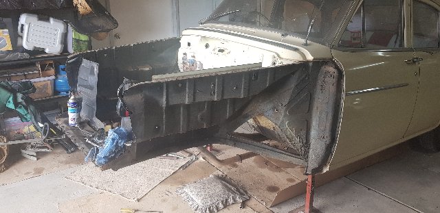 and this 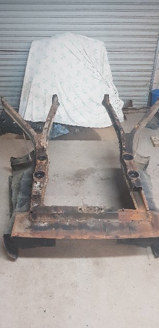 and this  and...................more to come. |
|
|
|
« Last Edit: May 27, 2020, 10:07:31 AM by stinky »
|
 Logged
|
|
|
|
|
Rod
|
|
« Reply #1 on: May 25, 2020, 10:15:29 PM » |
0
|
and this 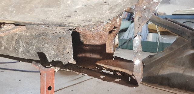 and this 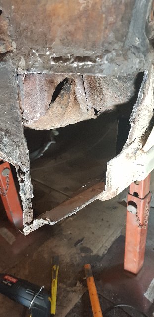 and this 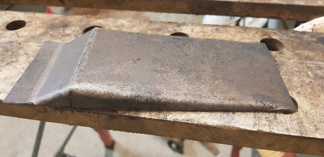 and this |
|
|
|
« Last Edit: May 27, 2020, 10:09:31 AM by stinky »
|
Logged
|
|
|
|
|
Rod
|
|
« Reply #2 on: May 25, 2020, 10:47:45 PM » |
0
|
I will try and keep it brief. Yes I started with a engine clean up. While motor was out I thought I would get rid of some rust in the front subframe. I started lying on my back driling spot welds etc and gave up as I thought it was going to be easier removing subframe as I did it a number of years ago on my ute. I plan to paint subframe and firewall so it was going to be easier to strip etc.. Subframe was / is in good knick. No suprises. However, passenger side attachment was rusted (Drivers excellent). Once I investigated I realised that a previous repair I had done as a young fella by a panel beater (30 years ago now) was just metal welded over the rust. So much so there was metal welded over the subframe bolt on that side. All of this was then covered up by black "s...t". I have now cut this out and will do it right. I think this why so many of us now do this ourselves because we know that to the best of out knowledge it will be better than the unknown. Has anyone got photos of what it should look like inside the A Pillar. I know you can now buy replacement panels for these sections and to be honest that would be the easy way but I see it a real learning experince for me to make these and a sense of occomplishment when done. I have looked at many photos of builds and have a good idea but unsure on what the guts should look like. I have read there is no crush tube between the inner and out but what is left of mine there seems to be one. 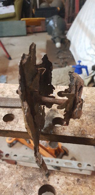 I have gained so much inspiration in watching everyones build. Rob I have look at your previous build and now the one you are on. Sounds like you are in a similar position now. This lockdown has made me sit back and get back doing what I love with these old girls. Keep up the great work everyone. You probably don't fully appreciate how inspiring you are to others. Cheers Rod |
|
|
|
|
Logged
|
|
|
|
|
Rod
|
|
« Reply #3 on: May 25, 2020, 10:48:57 PM » |
0
|
Oh can anyone tell me what I am doing wrong with the photo links. I have tried a few different ways. Some show, others don't.
|
|
|
|
|
Logged
|
|
|
|
|
Roybeth
|
|
« Reply #4 on: May 26, 2020, 07:27:12 AM » |
0
|
I usually find I can't put more than one link in a post - get that "forbidden 440" message , two if I'm lucky - use the preview function first before posting and if the pics don't show, delete one until they do and then do another post for more pics.
|
|
|
|
|
Logged
|
|
|
|
|
Longman
|
|
« Reply #5 on: May 26, 2020, 08:26:23 AM » |
0
|
Oh can anyone tell me what I am doing wrong with the photo links. I have tried a few different ways. Some show, others don't.
Are you using [IMG] tags? |
|
|
|
|
Logged
|
|
|
|
|
fcwrangler
|
|
« Reply #6 on: May 26, 2020, 08:51:10 AM » |
0
|
Hi Rod, there is no crush tube as such! It is a rectangular box section roughly 50x50x90mm. If you have a look at at my build page (My FC Rebuild),you will see how I repaired mine. Also there are some good shots of the bottom Apillar sections showing the measurements as well. These photos are of an original ute that has not been repaired. There are also reproduction panels for the inner and outer sections for bottom of the pillars.
Hope this helps you out,
Jim
|
|
|
|
|
Logged
|
on the seventh day: God Made Holden
|
|
|
|
ardiesse
|
|
« Reply #7 on: May 26, 2020, 10:44:54 AM » |
0
|
Rod,
What you think is a crush tube is the remains of the subframe bolt.
There's no "standard practice" when it comes to repairing the subframe mounts. I reproduced the box-section, but Mal W (I think) used a crush tube. The main thing is to get about 1/4" of metal thickness at the inner sill where the hole for the subframe bolt is.
It's a nice piece of fabrication you have done, but . . . the "pad" where the subframe bolts up is not in the same plane as the inner sill. As well as facing backwards slightly (as you have it), it should also face upwards somewhat. The axis of the subframe bolt is neither level, nor square to the sill.
Rob
|
|
|
|
|
Logged
|
Remember: if your Holden's not leaking oil, it doesn't have any.
|
|
|
|
Errol62
|
|
« Reply #8 on: May 26, 2020, 01:34:18 PM » |
0
|
It is square to the no 1 body member. At least the inner and outer subframe mount holes on each side all line up.
Sent from my SM-G973F using Tapatalk
|
|
|
|
|
Logged
|
|
|
|
|
Rod
|
|
« Reply #9 on: May 26, 2020, 10:58:51 PM » |
0
|
Hi All, Thank you for your responses. Never in my wildest dreams did I ever think I would have a go at this repair. I to were getting the 404 errors when posting photos. I have been using Photoimage but I might need to go back and use Imgur. Thank you Jim for the information you provided. I searched the threads extensively but I missed yours. Very thorough. I have enjoyed reading it from the beginning. The info on the box, original and fabricated will be of great use. Great work! Rob thank you also. I am fairly confident that I have the inner sill repair ready to go (I still need to add vertical pieces perpendicular to the base of the repair.. I made a template out of a Wheat Bix Box (Very thin but reasonable rigid). I measured numerous times, placing markings on the frame but to be honest I was reluctant to cut the rust away. I read your "First FC Build" and got many ideas, particularly in regards to the "jig". I made one similar and are confident of locating (I hope) the inner hole along with the angle of the "pad". This lines up with markings I made on the chassis. Would it be reasonable to expect not to drill the hole until a trial fit of the subframe has taken place. With a subframe bolt in place I can then get the exact distance to the other a pillar location?  One of the reasons I have come to this repair other than the obvious was that the bolt was seized good and proper both on the inner as shown and also on the outer where the previous repair, steel was welded over the top. What an interesting exercise it was to remove the subframe because of this. Was / is there a base plate separating the upper A Piller with the bottom A Pillar? ie: at approximate floor level (There is one on the other side but I suspect this was put in on the previous repair. When I replace the outer a pillar panel which I plan to fabricate from a learning experience. What suggestion on metal thicknes would you recommend. I have 1mm which I have been using for minor relative non structural repairs and 1.5ish mm which I have used for the inner sill repair. I am thinking this but I suspect it will be difficult to "mould". Errol62, thank you for the pointers about being square to the number 1 cross member. This is great to know as it confirms what I found when I put the jig together. On a side note, can anyone confirm that the holes with the inner subframe attachment and the outer attachment are in direct line. My crude measurements suggest yes, but I need to get appropriate size rod and confirm the alighnment with the other side and also using the subframe as well. Sorry to bore you all. As I said I get great confidence or at least building confidence in re-reading and following all your threads. It is amzing the amount of builds etc... that is going on due to this virus thingy. Cheers Rod |
|
|
|
|
Logged
|
|
|
|
|
Errol62
|
|
« Reply #10 on: May 27, 2020, 12:05:50 AM » |
0
|
Have you got a workshop manual Rod? Have a look at the body section. There is a diagram which demonstrates as I recall. I have a panel van project which I fitted cowl, firewall, dash and a pillars off another car, as well as floor from an auto. I had to fabricate the outer section of the no 1 body member and the entire inner sills. Ultimately you need to rebuild the rusted sections to fit your subframe. This is the best jig. Ill see if I can find some photos.
Cheers
Clay
Sent from my iPad using Tapatalk
|
|
|
|
|
Logged
|
|
|
|
|
Errol62
|
|
« Reply #11 on: May 27, 2020, 12:13:27 AM » |
0
|
 See how the screwdrivers through the inner mounts point parallel to the body member. Outers do the same. Sent from my iPad using Tapatalk |
|
|
|
|
Logged
|
|
|
|
|
Rod
|
|
« Reply #12 on: May 27, 2020, 10:04:40 AM » |
0
|
Hi Errol62.
Thank you for this photo. It is brilliant and this confirms my thoughts / questions. Therefore because of the parallel nature of both the inners and outers, if I was to run a rod on a specific side it will allow me to get the appropriate angle of the subframe bolt when I go to reconstruct the lower outer a piller.
This is a ripper. Thanks again.
Cheers
Rod
|
|
|
|
|
Logged
|
|
|
|
|
ardiesse
|
|
« Reply #13 on: May 27, 2020, 12:52:07 PM » |
0
|
Rod,
It is worth noting, though, that although the inner and outer subframe bolts are parallel to the No. 1 body crossmember, their axes are not collinear. Don't expect to be able to run a rod through the inner subframe bolt holes and pick up the outer subframe bolt hole.
Rob
|
|
|
|
|
Logged
|
Remember: if your Holden's not leaking oil, it doesn't have any.
|
|
|
|
Rod
|
|
« Reply #14 on: May 27, 2020, 02:26:03 PM » |
0
|
Hi Rob,
Well that throws a spanner in that idea. I was hoping to use this as a back up / confirmation of the jig I made.
Cheers
Rod
|
|
|
|
|
Logged
|
|
|
|
|
Rod
|
|
« Reply #15 on: May 27, 2020, 02:27:21 PM » |
0
|
Oh, for some reason the photos are now showing. I haven't done anything for this to occur. Has it been done in the background?
Rod
|
|
|
|
|
Logged
|
|
|
|
|
Errol62
|
|
« Reply #16 on: May 27, 2020, 03:30:20 PM » |
0
|
I reckon they are pretty close to being on the same axes, left and right rob, rod.
Sent from my iPad using Tapatalk
|
|
|
|
|
Logged
|
|
|
|
|
ardiesse
|
|
« Reply #17 on: May 27, 2020, 07:51:39 PM » |
0
|
You might be right, Clay, but one would need a "reference" body shell or subframe to confirm. The underbody dimension drawing in the shop manual doesn't have enough detail to make the call.
If the inner and outer bolt holes were on the same axis, life would be a lot simpler.
But I remember when turning up a set of "subframe-bolt-bullets" that the inner subframe bolts are 3/8" dia. and the outer bolts are 7/16" diameter.
Rob
|
|
|
|
|
Logged
|
Remember: if your Holden's not leaking oil, it doesn't have any.
|
|
|
|
mcl1959
|
|
« Reply #18 on: May 28, 2020, 08:45:03 AM » |
0
|
Rod, there is a plate inside the A pillar at about floor level. It is not structural but rather closes the gap so that if you drop a bolt when you are attaching the mudguards then it doesnt fall Into the sill. The plate is completely sealed around the edges with sealant from the factory.
Ken
|
|
|
|
|
Logged
|
|
|
|
|
Rod
|
|
« Reply #19 on: May 28, 2020, 11:12:03 PM » |
0
|
Hi Ken, So the plate would be there to prevent this?? 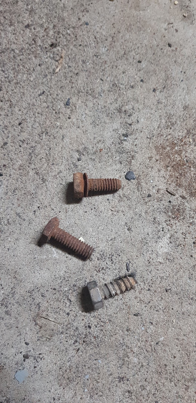 This is what I found at the front of the sill. I can't remember 30 years ago but I must have dropped them. It did notice that there is no upper nut" on the mudguard in question. I could understand the reason for the two machined bolts but the threaded sheet metal one is a mystery. It looks as it it has never been used. Fortunately or unfortunately I didn't find any sockets. The timing of your post is uncanny. Last night I have began gathering a template for this panel. Gee that is difficult. My plan was to make one even if it wasn't originally in place to prevent the misadventure of the bolts you have spoken about. Thanks again. Rod |
|
|
|
|
Logged
|
|
|
|
|


