|
Harv
|
 |
« on: June 25, 2013, 10:14:03 AM » |
0
|
Ladies and Gentlemen,
As promised, here is a start to the Norman supercharger thread.
Having finished the grey motor crashbox guide, it's time to start a new project. My intention this time is to write a Guide for Norman superchargers. What worries me a little is that Norman superchargers are very thin on the ground. Whilst I was able to lay my hands on quite a few carbs, gearboxes and heaters to play with and compare, the chances of doing so with a Norman are pretty slim. It also takes quite a bit of time to write a Guide, and the info must seem to "fall into a black hole" in the interim. To address these concerns, I'm going to write the Norman Guide by publishing dribs and drabs on a single forum thread (one near-identical thread each on the FB/EK, EJ/EH, FE/FC and FX/FJ forums). This means that you get the info earlier, and offers an opportunity for people to comment/add info as we go along (instead of me reverse-engineering by pulling apart several examples). Some weeks there will be an update, some weeks not... depends on how busy I get. I'm also hoping that by publishing dribs and drabs that it will encourage people to bring forth some info to help complete the picture. Once the info is complete, I'll pull it all together and pdf it as a Guide.
The Guide that will come from this thread aims to provide some information regarding fitment of Norman superchargers to early Holdens, and primarily FB/EK Holdens. It will contain:
some of the theory behind sliding vane superchargers,
historical information on the production and use of Norman superchargers,
practical information on the identification, disassembly and reassembly of Norman superchargers, and
guidance on tuning, replacement parts and overhaul techniques.
The Guide does not aim to be a detailed textbook on all topics of supercharging, nor does it present the basics of how supercharging works. For information of this nature, Id strongly recommend the following books:
Supercharge! by Eldred Norman, 1968
"Supercharged! Design, Testing and Installation of Supercharger Systems" by Corky Bell, 2001
"Supercharging Performance Handbook" by Jeff Hartmann, 2011 or
Turbochargers by Hugh MacInnes, 1984.
Whilst the Norman supercharger will greatly increase the performance of a Holden grey motor, it will not deliver the neck-snapping, tyre frying, 9-second quarter mile performance that many people associate with supercharged engines. Like most grey motor performance equipment, Norman superchargers can be likened to going faster
slowly. I will assume in the discussion below that the reader is interested in historic speed equipment that is period correct (i.e. that the basic equipment could have been purchased in the 50s-60s) yet operable (i.e. that some concessions will be made to allow the supercharger to function with modern fuels, registration laws and with materials that are currently available). I will also assume that the reader has been able to get hold of a Norman supercharger, but is missing some or all of the ancillaries (manifold, carburetor, water injection, overhaul parts) required to get it running.
Whilst the Guide will use FB/EK Holdens as an example, much of the information is applicable to other early Holdens. Please bear in mind that the Norman supercharger was not an original fitment to early Holdens, and hence that limited documentation is known to exist. Much of the information below is drawn from internet forums, discussion with enthusiasts and common sense. I will use photos and other information from a wide variety of sources, particularly from the forums if anyone is offended by my use of the material, feels I have breached copyright or needs recognition, please let me know and I will correct the issue immediately. Equally, I will make opinions and draw conclusions on some of the information I have found and equipment I have owned, and have cross-referenced some material - if anyone believes that I have made an error (or knows a better way to do something), please let me know and I will update the document... after all, the main purpose here is to help other early Holden enthusiasts.
Like all things automotive, installing, operating and maintaining a Norman supercharger comes with a risk. Leaking fuel lines can lead to fires, jammed throttles can lead to out-of-control vehicles and items dropped down a carburetor throat can cause massive engine damage (amongst other hazards). Any advice contained in this document is to be taken at the readers risk qualified mechanics should be consulted where appropriate.
|
|
|
|
|
 Logged
|
|
|
|
|
Harv
|
|
« Reply #1 on: June 25, 2013, 10:14:54 AM » |
0
|
As a start for this post, lets take a quick look at supercharger theory, and specifically where the Norman fits in. Supercharger is a collective term for a large variety of equipment, each with the same practical purpose: to jam as much air as practicable into an engine, along with more fuel, to make more power. When the word supercharger is used, the most common image that comes to mind is a polished GM 6/71 Rootes blower sitting on top of a Chev V8, with an injection bug catcher sitting on top. However, superchargers are a lot more diverse, and can be taken to include: turbochargers, nitrous oxide (often referred to as chemical supercharging, and tuned inlet runners (ram air). In general, a supercharger can be considered to be a mechanical machine that compresses air (and sometimes fuel) that is driven by the engine. A turbocharger is the same type of device, but driven by exhaust gas pressure. If we put chemical supercharging aside, superchargers are of two basic types: a) Positive displacement: in this type the supercharger sucks in a set volume (or packet) of air, and then forces out the same packet of air. This is similar to the way that a piston engine works (valves open, suck in a set volume of air and fuel, close the valves, compress and power, then open the valves to let the gas out). These types of supercharger have a displacement, or volume or air that is sucked in for every revolution of the supercharger drive shaft. b) Dynamic: in this type of supercharger the amount of air sucked in is dependant on the speed of the drive shaft, with some churn or slippage inside the supercharger casing (i.e. a packet of air might be sucked in, then some of the packet recirculated a bit before being pushed out again). This is similar to the way that a grey motor water pump works. These types of supercharger do not have a displacement, but instead are described by a compressor map (a fancy drawing that shows pressure and flow changing with supercharger speed, similar to the pump curves used in heavy industry). Superchargers are also defined by whether they have an internal compression ratio or not. An internal compression ratio means that the air is compressed inside the supercharger before leaving the machine. Superchargers that do not have an internal compression ratio do not compress the air inside the casing. Rather, they suck air in and push it out, with the compression being done by mooshing the air up inside the cylinder head (more on this later). Sometimes the term blower is used to distinguish superchargers that do not have an internal compression ratio (as they just blow the air through without compressing it). However, this should not be relied on, as blower has become synonymous with most types of supercharger (similar to the way that the terms huffer, snail, compressor, charger and turbo are bandied about). Examples of both positive displacement and dynamic superchargers are shown in the diagram below. Note that I have also added chemical superchargers (nitrous and nitro) to the chart. 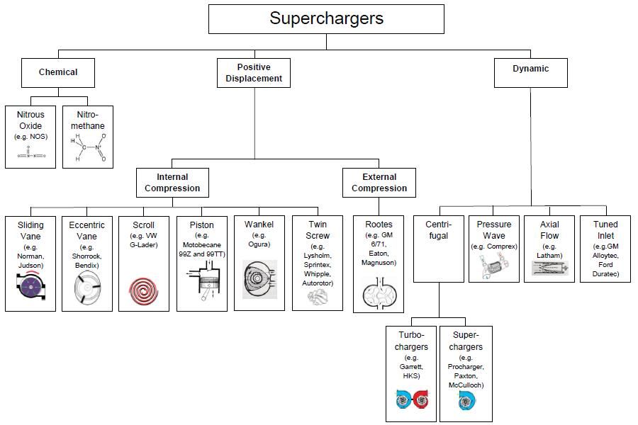 Note that the Norman supercharger is a positive displacement machine, and that it has an internal compression ratio. Enough for a first post - happy to hear commetns and input please. Cheers, Harv (deputy apprentice Norman fiddler). |
|
|
|
|
Logged
|
|
|
|
|
fe350chev
|
|
« Reply #2 on: June 25, 2013, 09:47:21 PM » |
0
|
Thanks for this. Younger guys like me can appreciate old school technology as well as the many technological developments that have occurred, whilst we continue to practice on our project cars. That is why I have one that will be standard and one to play with. Even if someone says to me "Don't mess with a grey", I don't listen because I want to try things for myself because I want to experience it. It's like telling us not to bother going to a drive-in, because indoor theaters are more comfortable. Well my young boys absolutely loved the drive in and they enjoyed the stories of when we attended as kids their age. Same thing here, it gives the older generation a chance to engage with the younger blokes on the forum by mutually respecting different era's in motoring history. I feel the need to share some reading, which is widely available on the internet, but this article is very interesting about the "Miller Cycle" concept and how it can relate to supercharger ideology. Maybe guys on here could take some tips from developments when selecting camshafts etc for their grey. I think it would be possible to do some sort of mechanical variable valve timing, even on a grey to get this effect. Things like this could become a long term 20 year project for me, with inspiration from the likes of Waggot. Remember the old Renault Pneumatic activated valve spring system, this could be combined with Miller Cycle philosophy and old school pneumatics to somehow create a cam sensory arrangement with positive airflow to the valve actuator, that activates the inlet valve only with a high lift but late on the duration (for the inlet valve only), to create the miller cycle effect. http://en.wikipedia.org/wiki/Miller_cycleEven partially open would increase efficiency and would not need to replace an inlet lobe because it would take over the after the lobe has done the initial "lift".    http://en.wikipedia.org/wiki/Pneumatic_valve_springs http://en.wikipedia.org/wiki/Pneumatic_valve_springsI would like to make a concept motor using a four stroke brigsy engine or the like with alloy head, that way if it doesn't work i can just tig it up. People like FC Hoon will already have air pressure in their car! I have never seen a miller cycle Nissan engine before. It seems all the more possible to do this with an overhead valve arrangement using the valve stem somehow. Food for thought from the bush whacka. |
|
|
|
|
Logged
|
Deano
Current Rides: 1958 "Black and White Taxi" FC special Sedan, 1957 FE special Sedan, BA Futura, 2015 VF Commodore, 1956 Austin Tipper Truck
|
|
|
|
Harv
|
|
« Reply #3 on: June 26, 2013, 06:57:03 AM » |
0
|
Gotta love trying something different with a grey. I've got a set of Triumph Lucas mechanical fuel injection under the bench, and have dreams of a blown and Norman injected grey.... stuff to think through on a quiet day.
Cheers,
Harv
|
|
|
|
|
Logged
|
|
|
|
|
fe350chev
|
|
« Reply #4 on: June 26, 2013, 10:46:26 AM » |
0
|
Exactly!
|
|
|
|
|
Logged
|
Deano
Current Rides: 1958 "Black and White Taxi" FC special Sedan, 1957 FE special Sedan, BA Futura, 2015 VF Commodore, 1956 Austin Tipper Truck
|
|
|
|
Harv
|
|
« Reply #5 on: July 19, 2013, 06:42:40 AM » |
0
|
Righto, time for the second instalment of the Norman Guide. Having tackled the basic types of supercharger, lets take a look at the basic theory of a vane supercharger. Sliding vane compressors are positive displacement machines (as are Rootes superchargers), meaning that they draw in a parcel of air, and move that individual parcel through the machine to the outlet. This is different to say a turbocharger or centrifugal compressor, which are not positive displacement (they have a lot more slip of the air inside them). 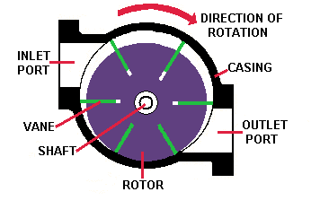 Where the sliding vane compressor rotor is mounted eccentrically (like a Norman supercharger), the air moving through the compressor is compressed within the casing. In this case, the compressor is said to have an internal compression ratio. The image below shows an eccentric compressor. 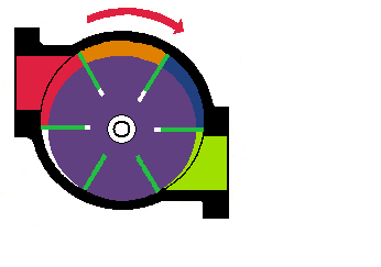 Air moves into the inlet port (red area). As the rotor turns (in this case clockwise), air is drawn into the orange area to fill the vacuum caused by the departing vane. As the vanes continue to rotate, the next vane passes the inlet, trapping the air between the two vanes shown either side of the orange area. The rotating vanes then move this parcel of air towards the blue area. Due to the eccentricity between the rotor and housing, the volume of the blue area is smaller than the orange volume, causing the air to be squeezed into a smaller space (compressed). The vanes continue to rotate, allowing the parcel of compressed air to flow out the outlet port (green area). When the sliding vane compressor rotor is mounted centrally (as per the image below), the air moving through the supercharger is not compressed within the casing (the compressor is said to have no internal compression ratio). 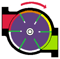 This is a common set-up in air tools. Whilst the turning rotor draws in air from the red to the orange to the yellow areas, the volume of the orange and yellow areas is the same. This means that the air is not being squeezed into a smaller space
just pushed along. The air then moves to the green area, exiting through the outlet port. In a supercharger, this air moves into the inlet manifold, and is smooshed up against the engine inlet valves that are shut. This smooshing provides the compression. Superchargers of this type, where the compression happens outside the supercharger, are said to have no internal compression ratio (just like Rootes blowers) - they compress the air in the inlet manifold, not the supercharger. So how is the sliding vane compressor (like a Norman) different to an eccentric vane type compressor (like a Shorrock)? In an eccentric vane compressor, the vanes are not free to move like a sliding vane machine. Instead, they are fixed (often riveted) onto a central carrier see image below. 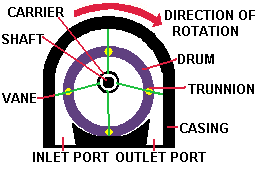 The vanes in an eccentric vane compressor do not rub on the casing (unlike a sliding vane compressor), but instead have a fine clearance (around 0.004). The vanes are mounted in an eccentric drum, and are carried in trunnions. As the drum rotates (carrying the vanes around with it), the eccentricity forces the vanes to protrude more or less. The figure below shows the gas passing through an eccentric vane compressor (from red to orange to yellow to blue). 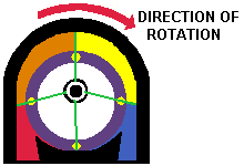 Notice that the vane at the bottom is almost buried in the drum, whilst the vane at the top protrudes from the drum quite a bit. The fine tolerances and differing internals make the eccentric vane supercharger significantly more complex than the sliding vane supercharger. Ok, enough for your second instalment. Next time around, I'll tackle supercharger capacity. As a reminder, if anyone has any Norman parts, whole blowers, photos or anecdotes that they want to sell, I am very much interested. I am also interested in having a "loan" of your Norman to help write this Guide if that suits. So far, I have five Normans lined up to compare... this Guide is looking like a winner. Cheers, Harv (chief deputy Norman apprentice). |
|
|
|
|
Logged
|
|
|
|
jack_fc
Senior Member

 Offline Offline
Model: FC
Posts: 745
SouthWest Coast, Victoria

|
|
« Reply #6 on: July 19, 2013, 08:51:34 AM » |
0
|
Another gem in the making! Thanks Harv (maybe you should consider a temporary name change to 'Norm'... ) |
|
|
|
|
Logged
|
"when I was a young lout, it was all about sex, drugs, rock'n'roll, beer and hot Holdens. Now I'm an old lout, but I've still got the old Holdens and beer..."
|
|
|
|
Harv
|
|
« Reply #7 on: August 05, 2013, 02:21:42 PM » |
0
|
Ladies and gents, As a prelude to the next installment, I will use this post to show the Norman superchargers which will be discussed, pulled apart, overhauled, reassembled and run during the course of writing this Guide. Note that I am confident of the name of only the Type 65 Norman
and only then because the name is (literally!) cast into the side of the casing. There are a lot of names bandied about (eg Type 70, Type 110) but I am not confident where people have drawn these from... other than Type 70 that I have also seen cast into casings. I have seen the Normans similar to the Large Normans shown below labeled as Type 110, but it does not line up to the capacity, nor is it stamped/cast into the casing. I have seen Normans with 75 stamped into them labeled as Type 75s), but again only because of the stamping (in which case my small Norman below would be a Type 45 as it has 45 stamped into it
yet I have never heard of a Type 45). All up, the names seem a mess for now, so I will use the simple names in red below for clarity. Maybe the forum postings will attract some answers as to how Normans are named in the long run. The first supercharger I will label as " Harv's small Norman". It has "45" stamped into the casing, and is a cast casing, four vane rotor, cross-ribbed unit: 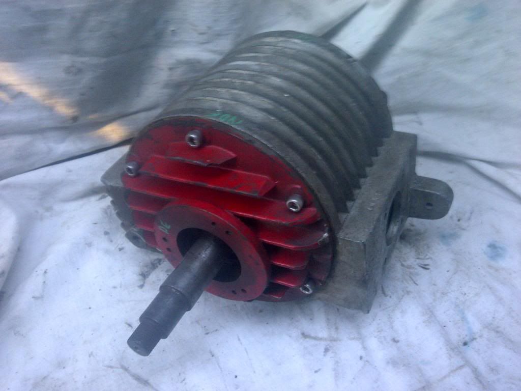 The second supercharger I will label as " Harv's large Norman". It has a serial number stamped into the casing, is a split extruded casing, three vane rotor, longitudinally ribbed unit: 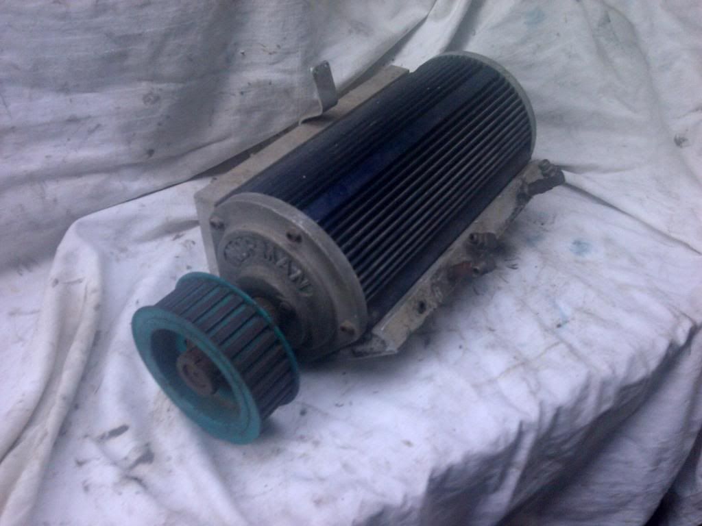 The third supercharger I will label as " Harv's watercooled Norman". It is a cast casing, four vane rotor, longitudinally ribbed unit. 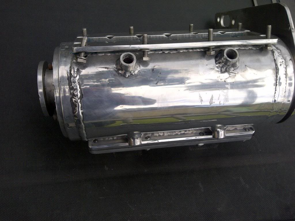 The fourth supercharger I will label as " Gary's Type 65 Norman". It is a cast casing, four vane rotor, cross-ribbed unit: 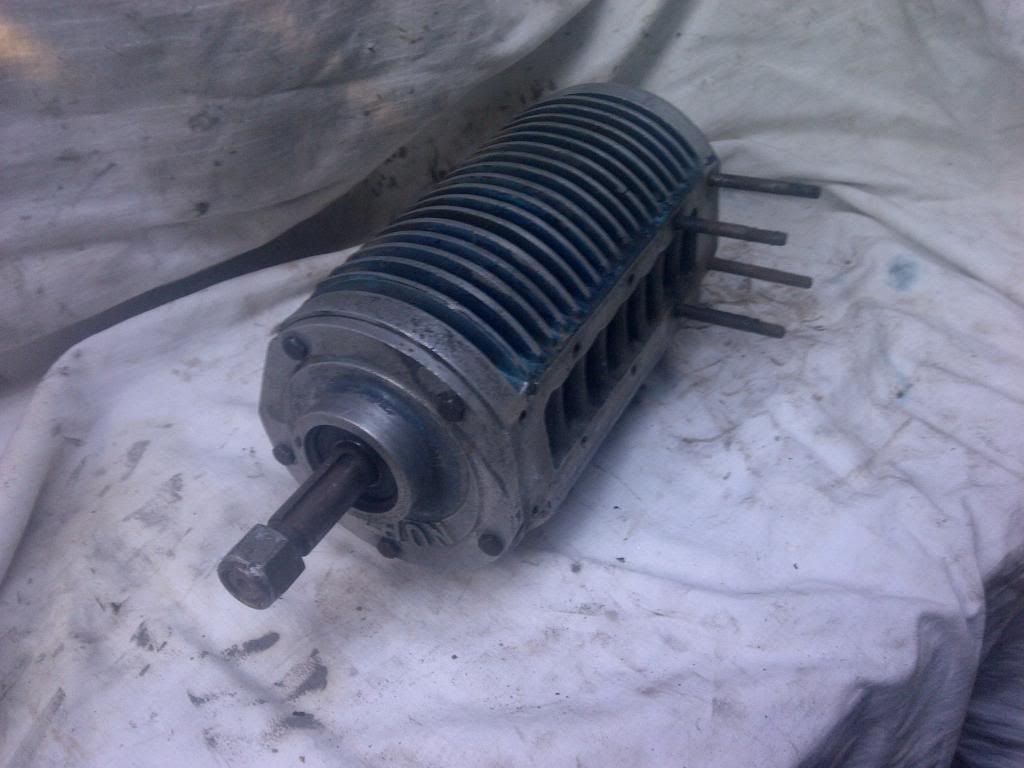 The fifth supercharger I will label as " Gary's large Norman". It has a serial number stamped into the casing, is a split extruded casing, three vane rotor, longitudinally ribbed unit: 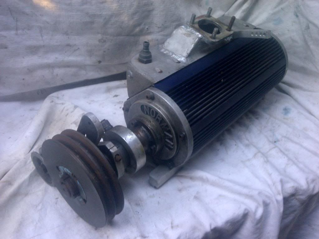 (this thing is a monster  ... but more on that later  ). Apologies in advance for the crap photos - more to come as I work these things over. Cheers, Harv |
|
|
|
|
Logged
|
|
|
|
|
Harv
|
|
« Reply #8 on: August 06, 2013, 06:48:28 PM » |
0
|
Orright, time for a post with a bit more substance (the pictures were nice, but a bit light and fluffy  ). This time around I'll deal with capacity. The capacity of a sliding vane compressor is determined by how much air the compressor sucks in between two consecutive vanes. In the image below, the compressor rotor has just turned to the point that the inlet port has been sealed off, trapping the air in the space shown in red. 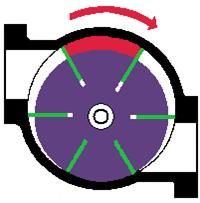 This volume of air, measured in cubic inches, is the volume of the air that one vane carries around per revolution. By multiplying by the number of vanes, the compressor capacity per revolution is determined. To measure this capacity on Norman superchargers, the end plate can be removed and the rotor turned by hand to the position shown. By using a pencil and paper, a rubbing of the area shown in red can be taken. The rubbing can then be ruled up with a grid of squares (say ¼x¼, where each square = 1/8 inch2), and the squares counted to estimate the area. By multiplying the area by both the length of the rotor and the number of rotors, the compressor capacity per revolution is determined. As examples, the Norman superchargers in my photos above have the following capacities: Harvs small Norman: area of rubbing (by counting squares) = 2,261mm2 volume per rotor = 2,261mm2 x 150mm rotor depth = 339,150mm3 volume of supercharger = 339,150mm3 x 4 vanes = 1,356,000mm3 = 83ci Harvs large Norman: area of rubbing (by counting squares) = 2,435mm2 volume per rotor = 2,435mm2 x 298mm rotor depth = 725,630mm3 volume of supercharger = 725,630mm3 x 3 vanes = 2,176,890mm3 = 133ci. Harvs water cooled Norman: area of rubbing (by counting squares) = 1,717mm2 volume per rotor = 1,717mm2 x 345mm rotor depth = 592,365mm3 volume of supercharger = 592,365mm3 x 4 vanes = 2,369,460mm3 = 145ci Garys Type 65 Norman: area of rubbing (by counting squares) = 1,917mm2 volume per rotor = 1,917mm2 x 10 rotor depth = 486,918mm3 volume of supercharger = 486,918mm3 x 4 vanes = 1,947,672mm3 = 118ci Garys large Norman: area of rubbing (by counting squares) = 3,233mm2 volume per rotor = 3,233mm2 x 347mm rotor depth = 1,121,851mm3 volume of supercharger = 1,121,851mm3 x 3 vanes = 3,365,000mm3 = 205.4ci Comparing this to some common superchargers: 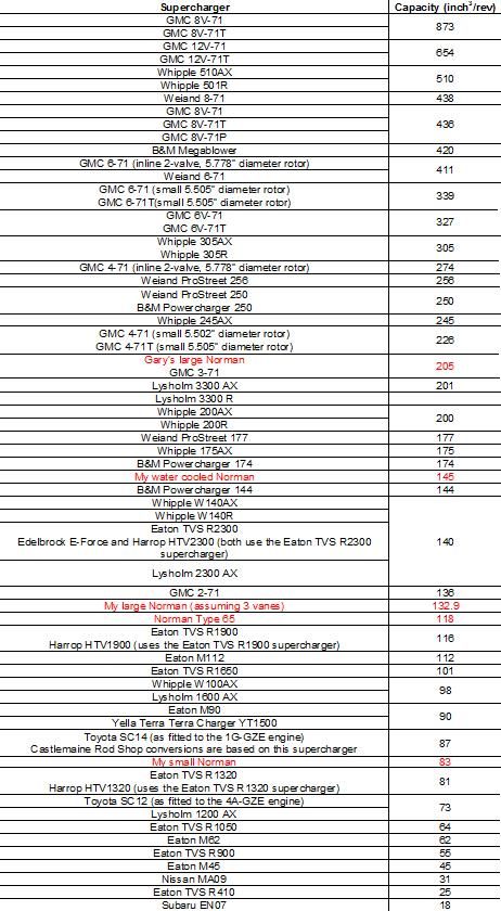 It is interesting to compare the Eaton M90 (as fitted to Holden Commodore VS (series II), VT, VX, VY L67 3800cc supercharged V6 engines) to the Norman superchargers
kind of like comparing Holdens newest and oldest. The Eaton M90 capacity (90ci/rev) is almost the same capacity as my small Norman (83ci/rev), and only half the size of Garys large Norman (205ci/rev). However, capacity is also a function of how fast you can turn the supercharger. The Eaton M90 (generation 5) highest efficiency is at 6000rpm, with the flow map going out to 13,500rpm (there appears to be no real redline for the Eaton, but efficiency drops off pretty smartly). http://www.eaton.com/ecm/groups/public/@pub/@eaton/@per/documents/content/ct_128485.gif By By comparison, the Norman supercharger as fitted to a grey motor is typically driven at engine speeds of maximum 4500rpm. This means that although the capacities are about the same, you can run a new Commodore supercharger about twice as fast and hence get around double the capacity (i.e. the new Commodore superchargers have about the same realistic capacity as Garys large Norman, and about double the capacity of the old grey motor Normans). Similarly, then Toyota SC14 (as fitted to the 1G-GZE engine) ran at 1.25 times crank speed, with a (crank) redline of 7500rpm. This gives a blower redline around 9500rpm, and hence an overall capacity similar to the Eaton M90. Sadly, I am not able to compare the capacity of the Normans to their sister supercharger, the Judson. Despite quite some searching and conversations with some Judson gurus, it appears that no-one has measured the capacities of these superchargers. The closest I can come is the smaller Judson was 5.125 X 4" diameter and was used on engines from 850 to 1300cc, whilst the larger Judson was 9.5 X 4"diameter, and was used on displacements from 1500 to 2500cc. Each used a 3" diameter rotor with 4 vanes. Cheers, Harv |
|
|
|
|
Logged
|
|
|
|
|
Harv
|
|
« Reply #9 on: August 12, 2013, 04:54:57 PM » |
0
|
Having looked at the capacity (flow) of Norman superchargers in the last post, it's time to think about pressure. The efficiency of a sliding vane compressor is dependent on whether the machine has an internal compression ratio or not. Where the sliding vane compressor rotor is mounted centrally (like in air tools), we have no internal compression ratio. As an example, assume the centrally-mounted supercharger is delivering 5 psi of boost, as shown below. 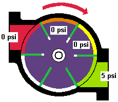 Because the compressor does not compress the air inside the casing, the 0 psi inlet pressure is also seen in the orange and yellow areas of the casing. As the yellow area of the casing is spun around to the green outlet, 0 psi air from the casing meets 5 psi air from the inlet manifold. The manifold initially flows air backwards into the supercharger casing, until the rotating vanes smoosh the air into the inlet manifold and compress it to 5 psi. This backwards and forwards flow reduces the compressor efficiency substantively, the same way that a Rootes compressor behaves. In the case of the Rootes compressor, this is one of the main reasons why Rootes compressor efficiency is low (around 55%) compared to centrifugal compressors (around 70%). Sliding vane compressors having an internal pressure ratio (where the sliding vane compressor rotor is mounted eccentrically, like Norman superchargers) have a higher efficiency than the example shown above. This is because the compressed air delivered from the casing does not flow backwards and forwards as it exits the exhaust port. However, the efficiency is also dependent on the location of the exhaust port. Ideally, the compressor should deliver the required boost pressure at the outlet (i.e. if we want 5 psi boost, that is exactly what gets spat out of the supercharger). Using our example from above of a compressor delivering 5 psi of boost, but assume an eccentric mounted compressor like the Norman. The image below shows how the pressure increases inside the casing. 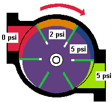 As the blue area of the casing is spun around to the green outlet, 5 psi air from the casing meets 5 psi air from the inlet manifold, and no energy is lost in backwards and forwards flow. However, if the discharge port is located closer to the inlet side (as per the diagram below), the compressor may not deliver the same pressure as the required boost pressure. 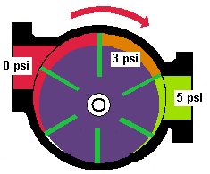 Whilst the gas is squeezed, the space it is being squeeze into (the orange area) is not yet small enough to increase pressure to our 5 psi desired example pressure
in the example we are only getting 3 psi. In this case, there will be some backwards and forwards flow during discharge (when the 3psi orange area opens up to the 5psi green area), and a resultant loss of efficiency. Similarly, if the compressor discharge port is located further away from the inlet side (as per the diagram below), the gas is squeezed more than is required for boost pressure. 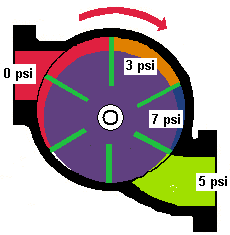 As the compressor begins to discharge, the gas expands into the inlet manifold. In the example above, the gas is compressed to 7 psi (blue area) before expanding into the (green) 5 psi discharge port. This over-compressing and expansion is again inefficient. |
|
|
|
|
Logged
|
|
|
|
|
Harv
|
|
« Reply #10 on: August 12, 2013, 04:56:15 PM » |
0
|
The chart below (which I have adapted from Compressors Selection and Sizing by Royce Brown) shows two cases either the discharge port being too close to the inlet, or too far from the inlet. The red area under the chart represents the energy lost (leading to lower efficiency) in each case. 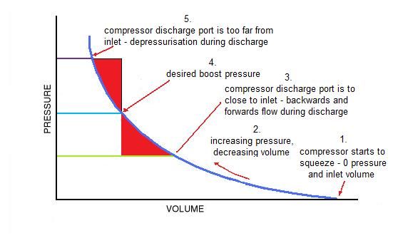 Looking at one parcel of air (between two adjacent vanes) moving through the supercharger, and targeting a boost pressure as shown at 4.: 1. We start with the supercharger sucking in air from the inlet manifold. We have zero pressure (just atmospheric pressure), and the air takes up just the inlet volume between the two adjacent vanes. 2. The rotor spins and we start compressing our parcel of air. Volume decreases and pressure increases. 3. If the compressor discharge port is designed to open at this point, we havent squeezed up to the pressure at 4. yet. Our air flows backwards and forwards during discharge, and we lose the energy shown in the lower red triangle. 4. If we keep squeezing (rotating), and our discharge port is positioned so the air is released at this pressure, then we are optimized. Nice smooth flow from the supercharger into the cylinder head. 5. If we still keep squeezing (rotating), and our discharge port is positioned at this pressure, then we have overcompressed. Our air will lose pressure once it is released into the cylinder head, and we lose the energy shown by the upper red triangle. OK, enough for one post. Next post we will see how to measure up an actual Norman supercharger, and then how to work out what the optimal discharge pressure is for that machine. Cheers, Harv (deputy apprentice Norman supercharger fiddler). |
|
|
|
|
Logged
|
|
|
|
|
NES304
|
|
« Reply #11 on: August 12, 2013, 05:14:59 PM » |
0
|
Whoa, good stuff mate!
|
|
|
|
|
Logged
|
|
|
|
|
fe350chev
|
|
« Reply #12 on: August 13, 2013, 04:26:07 PM » |
0
|
Thanks mate. |
|
|
|
|
Logged
|
Deano
Current Rides: 1958 "Black and White Taxi" FC special Sedan, 1957 FE special Sedan, BA Futura, 2015 VF Commodore, 1956 Austin Tipper Truck
|
|
|
|
Harv
|
|
« Reply #13 on: August 18, 2013, 02:58:10 PM » |
0
|
As promised, time to see just what pressure the Normans are designed for  For an existing Norman supercharger, the discharge port is fixed. We can then measure and calculate the compressor internal compression ratio, and can estimate the boost pressure which is optimal for the specific port location. To do this, we need: a) the inlet air volume, which we determined in the last post by using the pencil rubbing technique. This area is shown in the diagram below red, 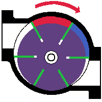 b) the inlet air temperature (this is the normal outside air temperature). c) the discharge air volume. In the image above, the compressor rotor has just turned to the point that the discharge port is just about to be exposed, with the air trapped in the space shown in blue. This volume of air, measured in cubic inches, is the discharge air volume. To measure this capacity on Norman superchargers, the end plate can be removed and the rotor turned by hand to the position shown. By using a pencil and paper, a rubbing of the area shown in red can be taken (just like we did with the inlet volume). The rubbing can then be ruled up with a grid of squares (say ¼x¼, where each square = 1/8 inch2), and the squares counted to estimate the area. By multiplying the area by the length of the rotor and by the number of rotors, the compressor discharge air volume is determined. d) The discharge air temperature. This can be calculated for different boost levels by a convoluted process. I will cover this in a future post. The pressures we will use for the calculations need to be in absolute pressure terms. This is achieved by taking the boost pressure (the pressure you would read on a gauge screwed into the inlet manifold) and adding 14.7 psi. For example, atmospheric pressure (0 psi boost) is (0 + 14.7 =) 14.7 psiabsolute. Similarly, the temperatures above need to be in absolute temperature terms. This is achieved by taking the normal temperature (the temperature you would read on a temperature gauge screwed into the inlet manifold), and adding 273ºC. For example, 35ºC temperature is (35 + 273 =) 308ºabsolute. We can then use the equation below to determine the optimum boost pressure for a given Norman supercharger: (inlet pressure x inlet air volume)/(inlet air temperature x discharge air volume)= (discharge pressure)/(discharge air temperature) Note that whilst the above process can be used to find the optimum (most efficient) operating pressure for a given sliding vane compressor, it does not preclude the supercharger being run at lower or higher boost
it just means that the compressor will not run as efficiently. As an example, consider my small Norman. For this supercharger, the inlet and discharge air volumes (calculated by the pencil rubbing technique) are as follows: a) Inlet air volume = 83 inchs3/revolution, and b) Discharge air volume = 73 inchs3/revolution. As an aide, notice that the discharge air volume is less than the inlet air volume - this particular supercharger, like all Normans, has an internal compression ratio (the air/fuel mixture is getting squeeeeeeeezed inside the supercharger). We can then start calculating: Inlet pressure = atmospheric pressure = 0 psi boost = (0 + 14.7) = 14.7 psiabsolute. Inlet air temperature = atmospheric temperature = 35ºC = (35 + 273) = 308ºabsolute Notice I am assuming a 35ºC day here
we could just of readily chosen a cooler day, but 35ºC is reasonable a fairly hot day when the engine will be working hard even with a cold air intake. Without a cold air intake, the supercharger air inlet temperature (aka the under-bonnet temperature) can be significantly higher. (Inlet pressure x inlet air volume)÷(inlet air temperature x discharge air volume) = (14.7x83)÷(308x73) = 0.0543 Discharge air temperature and discharge pressure are linked together, and can be modeled (we will do this in a later post
more on this later). If we assume that the motor is a typically asthmatic Holden grey motor (engine volumetric efficiency (VE) of 80%), that our Norman supercharger volumetric efficiency is 90% and that we still have a 35ºC day, then I can draw the following table: 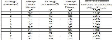 The right hand column calculates (discharge pressure/discharge air temperature)
sorry about the crappy label in the table. |
|
|
|
|
Logged
|
|
|
|
|
Harv
|
|
« Reply #14 on: August 18, 2013, 03:07:07 PM » |
0
|
Looking at the table above, we are looking for a value in the right hand column that is close to 0.0543. The table shows that this is around 3.7psi, inferring that the small Norman will run optimally at around this pressure (
for the curious, this would increase the factory EK Holden 75BHP by 25% to 94BHP, reducing the quarter mile from 18.7 to 17.3s). In practice, this means: a) We could run the supercharger at less than 3.7psi boost (for example 3psi in the inlet manifold) using a given pulley size. The supercharger will work, but it will compress the air to 3.7 psi before it lets it out into the 3psi manifold. There will be some popping as this over-compressed air expands into the lower pressure inlet manifold, and some loss of efficiency. b) We could run the supercharger at exactly 3.7psi boost, using a slightly larger smaller pulley (spin the supercharger faster). The air inside the compressor will be at 3.7psi when it lets out into the 3.7psi manifold. This is the most efficient operation. c) We could run the supercharger at more than 3.7psi boost (for example 5psi in the inlet manifold) by using an even smaller pulley (spin the supercharger even faster). The air inside the compressor will be at 3.7 psi when it gets let out into the 5 psi manifold. There will be some popping as the manifold air backflows into the supercharger, before being pushed out again by the turning rotor and smooshed in the inlet manifold back up to 5psi. Again, some efficiency will be lost. Repeating the above calculation process (pencil rubbings, calculations using the assumptions above, new table) for the other Normans: 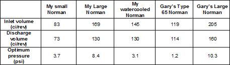 Of note, the older Normans (those made by Eldred) are designed for much lower boost pressures than the later Normans (those made by Mike Norman). This aligns well to the common belief that the early grey motor Normans were low rev, low boost, standard engine machines. The larger, newer Normans are designed for much higher boost probably due to advances in fuel quality, cylinder head flow, water/methanol injection and ignition that delay knocking and allowed them to deliver more power on red (and later) engines. An interesting feature of the small Norman is that the two end plates have been drilled to allow them to be rotated 180º (some of the later Normans have a locating pin to prevent this). Rotating 180º puts the rotor offset to the other side of the casing, and changes the inlet and discharge air volumes. 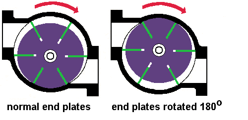 If end plates are rotated, the inlet air volume decreases from 83 to 24 inchs3/revolution and the discharge air volume decreases from 73 to 21 inchs3/revolution. This makes for a very small supercharger. If we undertake the same efficiency calculations: (Inlet pressure x inlet air volume)÷(inlet air temperature x discharge air volume) = 0.0545 The table shows that this is around 3.8psi, inferring that the small Norman will run optimally at around this pressure
not much change from the other way the end plates were. However, we now would have a much smaller capacity, and would need to spin the supercharger much faster to feed a grey motor
supercharger speed goes from 4,000rpm to 14,000rpm. Whilst Eldred suggested a destruction speed of 19,000rpm for his superchargers (Australian Hot Rod, November 1966), this is an awful fast speed for a fifty year old piece of kit with rudimentary bearing thrust control
not for the faint hearted. The upshot here is that when overhauling the small Norman supercharger care needs to be taken to orient the end casings correctly. Cheers, Harv |
|
|
|
|
Logged
|
|
|
|
|
Harv
|
|
« Reply #15 on: August 24, 2013, 02:47:56 PM » |
0
|
For this post, I am going to deal with the lineup of the Norman supercharger, and most notably the issue of suck-through versus blow-through. Superchargers are put together in two basic configurations: a) Suck-Through: in this configuration the fuel source (normally a carburetor) is located upstream of the supercharger. The supercharger thus sucks the air through the carburetor. The carburetor has no idea that the supercharger exists although the carburetor will need to flow more fuel/air to keep up with the extra engine power, it still operates under normal vacuum conditions just like a non-supercharged (naturally aspirated) engine. The supercharger in this case handles a mixture of fuel and air (i.e. an explosive air/fuel mixture exists all the way from the carburetor to the engine all the items shown in red below). 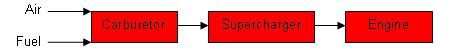 b) Blow-Through: in this configuration the fuel source (a carburetor or fuel injection nozzles) are located downstream of the supercharger. The supercharger thus blows air through the carburetor. The carburetor now operates under positive pressure instead of vacuum, often requiring modification to the carburetor (which was designed to operate under engine vacuum). The supercharger in this case handles only air, and the amount of piping and equipment holding an explosive air/fuel mixture (marked in red below) is reduced. 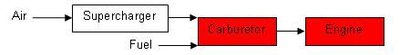 Norman superchargers are normally configured as suck-through. We will now work through why thus is the case. In very basic terms, we want to feed fuel and air into out engine in vast quantities. The image below shows the Norman supercharger connected up to the cylinder head of our Holden grey motor. 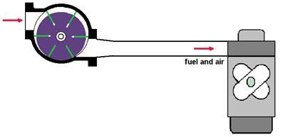 The first challenge that we face is that the supercharger internals have Bakelite vanes that rub against both the steel casing and the steel rotor slots. The vanes require lubrication to reduce the amount of friction (and hence vane wear). The incoming air does not do a great job of acting as a lubricant. We could add an oil squirter upstream of the supercharger, similar to the aftermarket squirter systems used to feed upper cylinder head lubricant (ValveMaster) when running unleaded fuel, or similar to the oilers used on workshop air tools. The image below shows this type of lineup. This type of squirter system, driven by engine vacuum, is commonly used on Judson sliding vane superchargers (the Marvel Mystery Oiler). 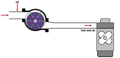 However, Eldred Norman found that this type of lubrication did not adequately lubricate the surfaces of the vanes in the rotor slots since centrifugal force tends to fling the oil drops against the casing. A better way of adding lubricant is to mix it in with the fuel. This oil/fuel mixture will then be fed much more evenly over the vanes. To do this, oil is added to the fuel tank (more on this later). By putting the carburetor upstream of the supercharger, the supercharger is fed both air and the fuel/oil mixture. The fuel/oil mixture then acts as a lubricant (and a heat sink) for the vanes. This lineup (suck-through) is shown in the image below. 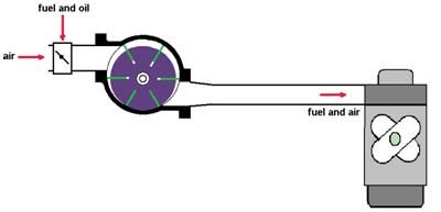 |
|
|
|
|
Logged
|
|
|
|
|
Harv
|
|
« Reply #16 on: August 24, 2013, 02:49:06 PM » |
0
|
We will now talk through Norman supercharger control and most notably the absence of Pssssshhht! Norman superchargers in suck-through configuration do not need a blow-off valve (sometimes called a dump valve, or BOV). We will now work through why this is the case. When the carburetor throttle plates are closed (for example during gear changes, as per the image below), the inlet air to the Norman supercharger is closed off. 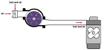 A slight vacuum will develop between the carburetor and the supercharger, though not a huge one. The supercharger inlet is not fed any air, and hence does not make a huge amount of pressure at the outlet. Boost remains (relatively) stable, and the supercharger does not see a huge load increase. However, if a blow-through configuration had been utilized (as per the image below, shown with the throttle plate open) then a different phenomena occurs. 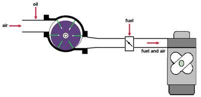 When the throttle plate closes, the supercharger has nowhere to discharge to. The inlet to the supercharger is still open, letting the machine suck in air. Because the Norman supercharger is a positive displacement machine, it will keep sucking in and compressing the air, mooshing it up against the closed throttle plate. The trapped boost pressure thus rises rapidly
giving the engine one hell of a shock once the throttle plate opens again. Worse, the supercharger goes into a high pressure, low flow situation called surge (this can sound like chattering in the machine). Surge causes damage to bearings and shafts. To prevent surge, a blow-off valve would be required as shown in the image below. 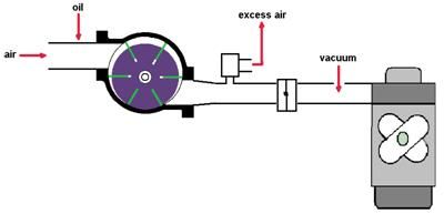 The blow-off valve is normally connected to the inlet manifold between the throttle plate and engine (I have not show this sensing line in the diagram for simplicity). When the throttle plate closes, our supercharger starts mooshing up boost against the closed plate. However, the inlet manifold between the throttle plate and engine goes into vacuum. The vacuum is sensed by the blow-off valve, which opens and lets out the excess air. In some cases the air is vented to atmosphere, giving the characteristic Pssssshhht! noise of late model turbo cars during gear changes. The loud noise of course is very, very sexy mate, and increases the libido. For those with no need for a libido increase, the blow-off valve can be plumbed back into the inlet manifold as shown in the image below. 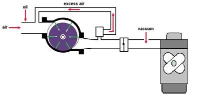 By venting off the excess air the supercharger can continue to spin and discharge. This prevents surge from happening. Many late-model vehicles run EFI, with the injection occuring after the supercharger (blow-through) and the throttle plate downstream of the supercharger. These vehicles are the ones commonly heard Psssssshhhhhting their way through traffic. |
|
|
|
|
Logged
|
|
|
|
|
Harv
|
|
« Reply #17 on: August 24, 2013, 02:49:41 PM » |
0
|
Blow-off valves are flow controllers they are designed to ensure a minimum flow through the supercharger and prevent surge. Again, because we are running the Norman supercharger in a suck-through lineup a blow-off valve is not required. Note that a blow-off valve should not be confused with overpressure protection (burst panels or relief valves) which are required on Norman superchargers. We will deal with overpressure protection next. As we have seen above, Norman superchargers are normally run in suck-through configuration, as per the images above. This means that all the equipment downstream of the carburetor contains an explosive air/fuel mixture the carburetor-to-blower manifold, the Norman casing, any intercooler used and also the blower-to-cylinder head manifold. The large the amount or size of the equipment, the greater amount of fuel/air mixture and hence the greater potential for an explosion. The ANDRA General Regulations refer to this as Banging the Blower an explosion inside the supercharger caused by a flame from the combustion process accidentally re-entering the supercharger, where fuel and air are present. Generally caused by a stuck or broken intake valve that normally would be closed during the combustion sequence. The more extreme the valve timing (more overlap) the more likely it is that the blower will bang, particularly at low rpm. Banging the blower can lead interconnecting hoses blowing off, manifold gaskets being blown out and stalling of the supercharger (which can snap vanes and bend rotors). In extreme cases the supercharger can be blown clear off the manifold
one of the reasons that blower restraints are used in some classes of racing. 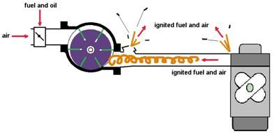 Belt drives are often used in Norman superchargers as they prevent a blower bang from stalling the crankshaft (they tend to slip instead). Given the risk involved, some form of overpressure protection is required downstream of the carburetors (despite Eldreds view that a standard car engine using boost up to only 5psi does not warrant pressure protection provided the manifold volume is not too great). One method to provide pressure protection is to utilize a burst panel. Burst panels function by venting the supercharger casing to ambient pressure with a non-reusable rupture disk or panel. Burst panels are mandated for some racing classes (for example for all ANDRA screw-type superchargers, for Australian Nostalgia Fuel Association Altereds, and for ANDRA Sport Compacts). Burst panels are often specified by guidance published by SFI ( http://www.sfifoundation.com/). SFI is a non-profit organization established to issue and administer standards for specialty/performance automotive and racing equipment. SFIs quality assurance specifications are sanctioned by CAMS, ANDRA and Speedway Australia. SFI Spec 23.1 covers Supercharger Pressure Relief Assemblies, and requires a burst pressure of 200-250psi, and an area of at least 10inch2 (12inch2 if multiple panels are used). This is a very large burst panel for a Norman supercharger, and is really intended for the large capacity race engines seen in drag racing (up to 500ci with 16/71 superchargers). Whilst a (smaller) burst panel could be utilized for a Norman supercharger, their operation is not conducive to road or track use (other than short-duration drag races) as a burst panel effectively puts the vehicle off the road. Whilst its not a big deal to change a burst panel at the drag strip, it can be a real pain in the Woolworths car park of a Sunday afternoon. An alternative to fitting a burst panel is to use a relief valve (sometimes referred to as pop-off valves, sneeze valves or sometimes as blow-off valves). The image below shows a relief valve fitted to our Norman supercharged Holden grey motor. 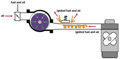 Relief valves operate similarly to the brass valve located on the side of residential hot water heaters. A spring holds the valve shut in normal use. As the supercharger manifold pressure increases, the spring is compressed, opening the valve and letting the pressure flow out to atmosphere. Once the pressure is low enough, the valve reseats and the vehicle can continue to operate (this is handy in the Woolworths carpark). I will come back in a later post and explain some more about a few more of the control issues - bypasses, wastegates and boost controllers (believe it or not some of that lot applies to Normans ). I will also delve deeper into relief valves, both period and new types. Cheers, Harv (deputy apprentice Norman supercharger mechanic). |
|
|
|
|
Logged
|
|
|
|
|
Harv
|
|
« Reply #18 on: August 26, 2013, 09:54:55 AM » |
0
|
So what about all that other stuff that the Zimm Pirates rant about Wastegates, Boost Controllers, Intercoolers, Timers and Bypasses? There are a number of pieces of supercharger and turbocharger equipment that are commonly referred to in magazine articles, or seen hanging off the front of late model turbocharged cars. Some do apply to the Norman supercharger, and some dont. A wastegate is a valve that diverts (bypasses) exhaust gas away from the turbine wheel in a turbocharger system. Bypassing some of the exhaust gases regulates the turbine speed, which in turn regulates the rotating speed of the compressor. By regulating the compressor speed, the maximum turbocharger boost pressure is controlled. Some wastegates are integral, where the bypassed exhaust flow rejoins the rest of the exhaust flow after the turbocharger. Alternatively, a "divorced" wastegate dumps the bypassed exhaust gas directly into the atmosphere. A divorced wastegate outlet pipe is commonly referred to as a screamer pipe due to the unmuffled noise they produce. Norman superchargers do not require a wastegate. The supercharger is directly coupled to the crankshaft (via a belt). The speed of the supercharger (and hence the boost pressure) is controlled by engine speed. Maximum boost is determined by the drive pulley sizes, and the ability of the engine to flow air into (and exhaust gas out of) the engine. A boost controller is a device to control the boost level produced by a turbocharged engine. It does this by changing the air pressure signal sent to the wastegate. Without a boost controller the wastegate is a simple air pressure/piston/opposing spring set up. The boost controller allows the air signal to be varied, and hence the response of the wastegate changed. This lets the wastegate open and shut only when required (and more consistently), reducing turbocharger lag. As a Norman supercharger does not have a wastegate, it usually also does not have a boost controller. Boost controllers are also sometimes made by electronically changing an engines engine management (EFI) software. This type of boost controller is occasionally employed on superchargers. In this case, it is used to make the car behave like it had an underdriven pulley system (low power) whilst putting around town, but also behave like an overdriven pulley system (high power) under load. Given that the Norman supercharger is normally run without complex aftermarket engine management, this kind of boost controller is also not applicable. Bypass valves are sometimes seen in supercharger systems. At low engine loads the power to drive the supercharger is not always better than the output gained. This parasitic loss can lead to poor fuel economy. The bypass valve open s when throttle loads are low and closes when throttle loads are high. With the bypass valve open there is no pressure being created across the supercharger. This allows the supercharger to not create parasitic drag at low speeds. With the bypass valve closed, all airflow is routed through the supercharger and boost is created. The bypass valve is purely used for economy under low load driving it is not a boost controller. Bypass valves can be internal (a valve that recirculates air inside the compressor casing) or external (where piping is used to plumb the air around the supercharger). The photograph below the internal (brass) bypass valve inside an Eaton MP90 supercharger inlet.  External bypass valves are used in some Norman superchargers, most notably the 110 Deluxe model. This supercharger had a hydraulic clutch driven by engine oil pressure. The clutch could be operated from a button on the dash, disconnected and connecting the supercharger drive at will. This is a bit different to a modern supercharger, which leaves the supercharging spinning when bypassed. When the Norman supercharger is disconnected, the engine becomes just like any naturally aspirated engine. It is however trying its hardest to suck fuel and air past the supercharger vanes
a hard task that would cause a huge loss of efficiency, even with the supercharger slowly freewheeling around under vacuum. To help the engine out, a bypass pipe and flapper valve system was installed to allow air to flow from the carburetor outlet straight to the inlet manifold, as per the image below: 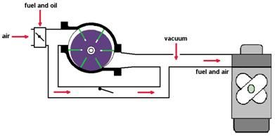 |
|
|
|
|
Logged
|
|
|
|
|
Harv
|
|
« Reply #19 on: August 26, 2013, 09:56:10 AM » |
0
|
The photograph below shows the bypass pipe linking the inlet and outlet side of the Norman supercharger: 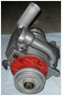 The same SU carburetor is used for both supercharged and bypassed operation. Under bypass mode the carburetor dashpot does not open fully, whilst under supercharged loads it opens more and more. This ability of SU carburettors to have a small venturi at low engine load gives good throttle response, and prevents fuel starvation. If a fixed venturi carburetor was used (for example a set of triple or twin standard grey motor Strombergs), the low engine load could give very little suck across the large (fixed) venturis, leading to little fuel flow and leanout. There are a number of downsides to having a bypass valve installed: Norman superchargers do not have internal bypass valves, so an external valve must be used. This takes up extra space in the engine compartment. if the bypass valve does not seal very well, it can cause loss of boost pressure under load (the supercharger will recycle on itself). most Norman supercharger owners are very unlikely to turn the supercharger off. Whilst the bypass will still open under low load conditions, the better fuel consumption is negated somewhat by the supercharger still being driven. Practically, if the Norman supercharger is one of the Deluxe models with a bypass then it will probably be used, if only for nostalgia sake. If the supercharger does not have a bypass installed, then it is does not require one. The compression of air/fuel in the supercharging process does generate heat. Some of the heat comes from the vanes scraping the casing, some from the vanes sliding in the rotor, and some from friction in the bearings. The heat from the vanes can be removed to some extent by water cooling the supercharger (some Norman superchargers have a water jacket around the casing which connects to the normal car radiator system). However, a substantive amount of heat is also generated by the compression process itself. The easiest way to visualize this heat is with a simple bicycle pump. Pump a bike tyre up to a decent pressure, then put your hand on the flexible rubber connecting hose the heat that you can feel is mostly the heat of compression. Heat is not a good thing in a supercharger. It can lead to poor lubrication, and increased bearing/vane wear. Worse, the heat does two things to the incoming air: a) It makes the air less dense (thinner). After all that hard work compressing the air, it is a shame that the air gets less dense, negating some of our hard work. The less dense air means less fuel/air mixture can be jammed into the engine, and hence less power than we had hoped for. b) The increased temperature makes the combustion process hotter, and moves us closer to the fuel igniting before we are ready. This pre-ignition is referred to as knocking (sometimes as pinging or pinking). Knocking can do a substantive amount of damage to an engine, including blowing out head gaskets, smashing piston ring lands and stressing bearings. To combat knocking we can some things (like retarding the ignition timing, adding water injection or running higher octane fuels), each of which comes at a price
usually less power and/or more cost. One way to combat this increase in temperature is to intercool the supercharger. Intercoolers are shown in the diagram below: 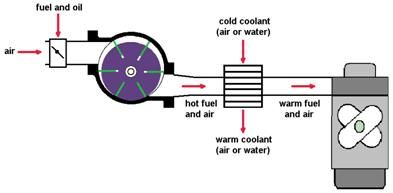 The benefits of intercooling are considerable
around 40-60% additional power from a supercharged vehicle. An intercooler may be: nothing more than a glorified radiator (referred to as an air-to-air intercooler). This is the shiny aluminium fixture often seen at the front of modern turbo cars after half the bumper bar and grille has been cut away, a full heat exchanger with the supercharged air on one side and water on the other (a water-to-air intercooler), a spray of cold compressed gas over the front of a glorified radiator, a box packed with dry ice with the supercharged air passing through internal tubes (kinda hard to top up the dry ice
this is mainly a drag race approach). Intercoolers were used on some Norman superchargers. For example the photograph below shows a Type 110 Deluxe supercharger with the (factory) air-to-air intercooler labeled as 6. This intercooler is a cast aluminium casing, with the air/fuel charge passing through. Cooling is achieved by the cooling fins alone. 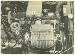 |
|
|
|
|
Logged
|
|
|
|
|


