|
cer444
|
 |
« on: July 03, 2005, 04:12:37 AM » |
0
|
Hi all I have just had my car at the wheel alighners and we have discovered I don't have enough +castor He has screwd the top adjuster as far back towards the rear of the car as it will go and the car has only has -2 degree castor (+3 degree is about ideal) Another problem we found which we think is causing the problem is the whole front cross member seems to be pointing down ie....The front outrigger is compressing the bottom half of the rubber squeezing the rubber out the sides. When we unscrewed the cross member bolts, removed the outrigger rubber and pushed the outrigger up towards the grille it gives + castor. It seems the rubbers at the rear of the crossmember that sit on top of the crossmember are not thick enough, we put about a 1/4" spacer in those rear rubbers and got it to about -1 degrees but it is still 4 degrees off our ideal +3 degrees. So in theory the outrigger needs to be lifted upwards towards the grill and the rear rubbers need to be thicker, sounds pretty easy to fix but it's not. What is causing the outrigger to push down?  Thanks Aaron |
|
|
|
|
 Logged
|
|
|
|
|
sgo
|
|
« Reply #1 on: July 03, 2005, 04:43:38 AM » |
0
|
The 4 bolts that hold your crossmember in have steel sleeves/tubes around them.I seem to recall some model holden having shorter ones on the front bolts. Maybe yours are the wrong way around or maybe they can be modified to give you more castor?? |
|
|
|
|
Logged
|
|
|
|
|
cer444
|
|
« Reply #2 on: July 03, 2005, 04:55:20 AM » |
0
|
Hi all
Just thought I might add that the whole front end was rebuilt.
New crossmember mounting rubbers were fitted, the crossmember mounting bolt shaft shims are in there correct place and had the correct pre-load on the lower crossmember rubbers.
|
|
|
|
|
Logged
|
|
|
|
|
cer444
|
|
« Reply #3 on: July 03, 2005, 05:03:01 AM » |
0
|
Hi all
sgo you must have just jumped in as I was adding to my first post.
As far as we can work out, those tubes/shims only place pre-load on the mounting rubbers and don't seem to affect the castor in the crossmember if the shims ar too short they take out the dampening affect and give a harder ride and send harsh shocks throuh the car.
|
|
|
|
|
Logged
|
|
|
|
|
craiga
Guest
|
|
« Reply #4 on: July 03, 2005, 06:47:20 AM » |
0
|
Aaron,
Have you checked the location and setting of the upper and lower inner A arm mounting?
From my recollection there is a tool or spacer to make this setting - if the A arm isn't positioned centrally then your castor setting will definately be affected.
Cheers,
Craig
|
|
|
|
|
Logged
|
|
|
|
|
cer444
|
|
« Reply #5 on: July 03, 2005, 07:36:28 AM » |
0
|
Hi all Thanks CraigA, I understand what you mean but that does no explain why the front outrigger is is trying to push itself into the bottom of the bracket. You can see the different gaps between the crosmember a chassis (front to rear) when you look at it from side on. Anyway if I can fix my alignment problem by moving the wishbone towards the rear of the car to give me more adjustment, I'd rather have a squashed outrigger rubber than a car that won't steer properly Would any one happen to have the spacer tool or know the width of this tool? ?? Thanks Aaron |
|
|
|
|
Logged
|
|
|
|
|
mcl1959
|
|
« Reply #6 on: July 04, 2005, 07:44:09 AM » |
0
|
Aaron, the shims do bolt up tight and they are different length, front to rear (there are in fact 5 sets of shims which should be trialled to achieve the correct distance specification when the correct torque is reached). If your bolts do not take up onto the shims without exceeding the torque spec then you probably have the wrong insulators. Are they nolathane or rubber?
Dont use nolathane - too harsh
There is also a thickness difference between FE-EH and HD/HR insulators.
You should have 3 insulators per corner (2 round and one square)
You probably have most of this stuff right, but I thought I would go through all the things which can possibly upset the crossmember mounting
In effect you should be able to bolt up the crossmember without the outrigger attached and have it sit in absolutely the correct position. The outrigger rubber only stops crossmember roll under braking load.
Ken
|
|
|
|
|
Logged
|
|
|
|
|
cer444
|
|
« Reply #7 on: July 04, 2005, 09:16:42 AM » |
0
|
Hi all
Ken- The insulator rubbers are rubber they came from spectrum rubber and I am assuming they have given me the correct ones.
What I have done (I don't know if this will work until I take it back to the wheel aligners) is put a nolathane 3/8 spacer on top the the rear insulator rubbers, this has now pushed the outrigger up to the middle half of the bracket.
I made another shim/tube to compensate for the added nolathane spacer.
This hopefully will give me more + castor, but now I have about a 1/2" gap at the rear of crossmember and the chassis.
I also tried to unscrew the upper wishbone a move that back, but the big nut bottoms out on the shaft before it locks on the wishbone
Thanks Aaron
|
|
|
|
|
Logged
|
|
|
|
|
Ed
|
|
« Reply #8 on: July 05, 2005, 08:23:09 PM » |
0
|
Guys,
my front end suffers exactly the same problem :-/
looks like i need to find the correct spacing tubes to sort this out?
currently my tubes are all the same length and this causes a problem as mentioned.
Ken, you mentioned 5 different set of shims available? what sizes are these?
thanks
Ed
|
|
|
|
|
Logged
|
in the shed
|
|
|
|
ACE
|
|
« Reply #9 on: July 06, 2005, 04:31:11 AM » |
0
|
Everything is explained in the FE Holden workshop manual. Page 57 and 58  ACE  |
|
|
|
|
Logged
|
|
|
|
|
Ed
|
|
« Reply #10 on: July 06, 2005, 04:36:01 AM » |
0
|
Everything is explained in the FE Holden workshop manual. Page 57 and 58 ACE thanks ACE, great however, I dont have a manual lol could somebody perhaps send me a photocopy? all these years and never owned a manual.. heh heh. this explains some of the idioitc questions i post.. Cheers Ed |
|
|
|
|
Logged
|
in the shed
|
|
|
|
SpeciFEcation
|
|
« Reply #11 on: July 06, 2005, 05:39:56 AM » |
0
|
I'll post a scan of the two pages tomorrow.
P.S. I tried tonight but several methods failed. I think I have a network or permissions issue.
|
|
|
|
« Last Edit: July 06, 2005, 07:47:04 AM by speciFEcation »
|
Logged
|
|
|
|
|
sgo
|
|
« Reply #12 on: July 06, 2005, 10:05:46 AM » |
0
|
I've got my front-end out at the moment and also looking at caster settings, and have come to the conclusion that if the rear bolt mounting is 6.4 ml longer than the front bolt mounting, when all tensioned up, the front end should be at a 2 deg. angle assuming the chassis is horizontal. The shim lengths listed in the manual are 19.8,18.3,16.7,15.6ml. each. |
|
|
|
|
Logged
|
|
|
|
|
SpeciFEcation
|
|
« Reply #13 on: July 06, 2005, 10:35:39 AM » |
0
|
|
|
|
|
« Last Edit: July 06, 2005, 10:36:55 AM by speciFEcation »
|
Logged
|
|
|
|
|
Ed
|
|
« Reply #14 on: July 06, 2005, 09:27:28 PM » |
0
|
thanks SpeciFEcation, those specs are handy.
It has made me aware of how wrong my front end (HR) may be set up tho...
firstly.. I do not have the 3rd insulator located under the x member. Does the HR front need this?
secondly I have no shims in place...again have I got it all horribly wrong?
It is little wonder the front end sits in the wrong position.
any help guidance appreciated.
Cheers
Ed
|
|
|
|
|
Logged
|
in the shed
|
|
|
|
Fast_Eddie
|
|
« Reply #15 on: July 06, 2005, 09:45:10 PM » |
0
|
Ed,
Buy a manual?
Regards
Ed
|
|
|
|
|
Logged
|
|
|
|
|
Fast_Eddie
|
|
« Reply #16 on: July 06, 2005, 09:52:30 PM » |
0
|
Here is a photo of the spacing tool. Actually, it is a photo of a magnificent front end with the spacing tool sitting on a piece of hessian. 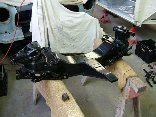 Call me on 0408 200 299 at 9pm on Thursday night (when I'm next at the shed) and I'll let you know the dimension should you still require that information. |
|
|
|
« Last Edit: July 06, 2005, 09:54:34 PM by Fast_Eddie »
|
Logged
|
|
|
|
|
sgo
|
|
« Reply #17 on: July 06, 2005, 09:52:39 PM » |
0
|
Use the HR insulators under the front -end, they're a square rubber pad about 1/2" thick. I made up shims all the same size and the front-end aligned ok, but might try the correct method this time?  |
|
|
|
|
Logged
|
|
|
|
|
Ed
|
|
« Reply #18 on: July 06, 2005, 10:30:42 PM » |
0
|
Ed,
I have the FX-HR manual which doesnt contain info to this depth.
LX torana manual for various wiring anomalies and steering stuff.
HX manual for engine bottom end specs
VN Commodore manual for wiring EFI and engine top end.
I dont really want another manual.
Front end looks nice, I managed to space out my control arms using 2 sockets, this is on an HR front however, so your spacer tool may differ?
SGO,
Rectangular HR rubbers
will get some, also I think I will just turn down an old spacer tube into the appropriate length shims using the 6.4 mm u gave as a guide.
CER444,
Sorry for hijacking your thread, hopefully this has been beneficial in your quest to gain the correct castor as well.
Thanks
Ed
|
|
|
|
|
Logged
|
in the shed
|
|
|
|
sgo
|
|
« Reply #19 on: July 07, 2005, 12:37:40 AM » |
0
|
ed, my rear tubes are 95ml. front ones are 92.5ml (stock?) and shim ones are all 12.5ml.
I didn't check how it sat relative to the chassis before I pulled it out, but alignment was fine.
|
|
|
|
|
Logged
|
|
|
|
|


