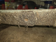
The addtional two bottom leaves do not taper and have square ends with rounded edges. The pins and bolts holding it all togehter have been replaced with metric ones - potentially by the previous owner who had started the restoration prior to his passing when the ute was put back into the shed for another twenty odd years.
It had been suggested to me that they may be lowering springs that were used instead of blocks. However, when I pulled the leaf pack apart it didn't take much effort on the clamp to pull the leaves in to undo the bolts; so I don't think that they were performing a lowering function.
My theory from the design was that they were overload springs but none of my internet research privided any leads. I had previously searched the forum but couldn't find any related info but went back and searched the Accessory of the Week thread and I found this reference to Rogers Overload Shock Absorber Leaves.
 . You can find the full post here: https://forum.fefcholden.club/index.php?topic=13115.msg78351#msg78351
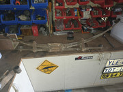
So it looks like it is a set of standard ute leaf springs that have been "uprated" to constant load springs with the addtion of two overload leaves at the cost of 7 quid back in the day. I have been tossing up the benefit of removing them to lower the unsprung weight and improve her handling v's keeping them as part of her history.
I have decided to clean them up as found, give them a coat of paint for protection and replace the wear pads and bushes and put it back together. My old girl will probably not be carrying anthing more than a picnic table, a couple of fold up chairs, an esky and a couple of bags in her old age, but the overload springs will be an acknowledgement to her working life.