Jolls
nsw-club
Senior Member

 Offline Offline
Model: FC
Posts: 388

|
 |
« on: August 06, 2024, 05:54:00 PM » |
0
|
Hi Team I have located what I believe is an original Air Chief radio from an FE/FC. It is in pretty average condition. 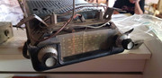 I expect that it is an early vibrator driven radio as opposed to the transistor type. Can anyone confirm that what I have found is what I think it is? Does anyone have the schematics for such a radio that I could use to try and bring it back to life? I have no experience with radios at all so thought this would be a great opportunity to learn some new skills while I try to pring her back to life. I know that I can purchase a repro fascia and radio dial face so the cosmetics can be done pretty quickly. If I can bring her back to life it would be great - if not I have a bluetooth AM/FM receiver that I can transplant into the back as a last resort. Thansk in advance for your advice. Cheers |
|
|
|
|
 Logged
|
Cheers n Beers
Jolls
|
|
|
|
Errol62
|
|
« Reply #1 on: August 06, 2024, 07:29:39 PM » |
0
|
The Qld. fb ek club president Greg Bell, is a retired avionics engineer and plays with this sort of thing. I would say it is a valve job almost certainly, given the size and vintage, by appearance. I know FB EK were a hybrid, using both valves and transistors. If you dont have any luck otherwise on here I can put you in touch with him.
Sent from my iPad using Tapatalk
|
|
|
|
|
Logged
|
|
|
|
|
ardiesse
|
|
« Reply #2 on: August 06, 2024, 07:56:26 PM » |
0
|
Craig,
Yes. It'll be an Air-Chief model RM: twelve-volt, six-valve radio with a vibrator power supply. I've got the schematics. I have an RM from an FE at home, but it's missing most of the front panel components.
The good news is that these are about the best-performing AM radios you can get, and the valves themselves are the most reliable components.
The bad news is . . . well . . .
(i) Expect the vibrator no longer to work. I've got circuit boards for a solid-state replacement.
(ii) They were wired with rubber-insulated wire. It will all have perished and will need replacing.
(iii) All the paper and electrolytic capacitors will have to be replaced.
(iv) The tuning control (on the left) passes through a rubber cup-cum-universal-joint. This perishes and falls apart.
(v) The years will not have been friendly to the coils, but this is a lesser problem than the previous four.
(vi) If you pop the covers off (you just need to pry them off with a narrow-bladed screwdriver) you'll notice that the radio's wired like someone emptied a two-litre ice-cream container full of components into it and soldered them down where they lay. But hey, while you've got the top cover off, you can check whether the tuning mechanism still works.
So, yes, I have worked on a few of these over the years. Definitely not for the faint-hearted, but most satisfying when you get it going and tweaked up to best performance.
And I won't recommend that you learn how to fix valve radios by starting on one of these. Go find a couple of five-valve mantel radios and practice on them first.
Rob
|
|
|
|
|
Logged
|
Remember: if your Holden's not leaking oil, it doesn't have any.
|
|
|
Jolls
nsw-club
Senior Member
Offline
Model: FC
Posts: 388
|
|
« Reply #3 on: August 06, 2024, 08:00:46 PM » |
0
|
The Qld. fb ek club president Greg Bell, is a retired avionics engineer and plays with this sort of thing. I would say it is a valve job almost certainly, given the size and vintage, by appearance. I know FB EK were a hybrid, using both valves and transistors. If you dont have any luck otherwise on here I can put you in touch with him.
Sent from my iPad using Tapatalk
Thanks Clay, appreciate the advice and the offer. If I get stuck I will let you know. If I can find the right doco I think I can fault find and conduct repair at component level - but doing it from first principles is beyond my comprehension. There is an ex Army Boffin (radio tech) that I know from my previous life that lives a couple of properties over so I can lean on him too if I have. I try to stay away from those queer trades unless I have to. I will be retiring soon so maybe time to teach myself something new. As an aside I also have a Vietnam vintage Mine Detector that I want to get up and running for my gradnchildren to use in the sandpit out the back. It was in service when I joined and I used one for many years; but it is a bit beyond my skill level and I have yet to locate schematics to enable testing. Definitely on my "to do" list though. |
|
|
|
|
Logged
|
Cheers n Beers
Jolls
|
|
|
Jolls
nsw-club
Senior Member
Offline
Model: FC
Posts: 388
|
|
« Reply #4 on: August 06, 2024, 08:29:22 PM » |
0
|
Craig,
Yes. It'll be an Air-Chief model RM: twelve-volt, six-valve radio with a vibrator power supply. I've got the schematics. I have an RM from an FE at home, but it's missing most of the front panel components.
The good news is that these are about the best-performing AM radios you can get, and the valves themselves are the most reliable components.
The bad news is . . . well . . .
(i) Expect the vibrator no longer to work. I've got circuit boards for a solid-state replacement.
(ii) They were wired with rubber-insulated wire. It will all have perished and will need replacing.
(iii) All the paper and electrolytic capacitors will have to be replaced.
(iv) The tuning control (on the left) passes through a rubber cup-cum-universal-joint. This perishes and falls apart.
(v) The years will not have been friendly to the coils, but this is a lesser problem than the previous four.
(vi) If you pop the covers off (you just need to pry them off with a narrow-bladed screwdriver) you'll notice that the radio's wired like someone emptied a two-litre ice-cream container full of components into it and soldered them down where they lay. But hey, while you've got the top cover off, you can check whether the tuning mechanism still works.
So, yes, I have worked on a few of these over the years. Definitely not for the faint-hearted, but most satisfying when you get it going and tweaked up to best performance.
And I won't recommend that you learn how to fix valve radios by starting on one of these. Go find a couple of five-valve mantel radios and practice on them first.
Rob
Thanks Rob, Appreciate the candid advice. Well - the good news is good. The bad news isn't all that bad. I have some experience working at component level so I'm not too daunted by the prospect. I will see if I can find a mantle radio to play with to learn on. As I mentioned to Clay I have a ex Army queer trade a couple of properties over so for a few beers I can probably get some one on one support. A few comments/question below if you don't mind sharing your wisdom. (i) Expect the vibrator no longer to work. I've got circuit boards for a solid-state replacement. I suspected that the vibrator would be gone as it is an electro mechanical component. (ii) They were wired with rubber-insulated wire. It will all have perished and will need replacing. I have dealt with similar cabling when I started out as an electrician - I know exactly what you mean! (iii) All the paper and electrolytic capacitors will have to be replaced. I have experience doing this so not too much of a problem - I guess finding the equivalent components will be the most difficult part. (iv) The tuning control (on the left) passes through a rubber cup-cum-universal-joint. This perishes and falls apart. Is this something that can be cast in resin? (v) The years will not have been friendly to the coils, but this is a lesser problem than the previous four. I hadn't considered this - I expect that they can be rewound if need be. Is this something you have learned on the side or do you have a background in this area? I have some experience as a sparky working on contactors and control circuits on process machinery so I'nm not a total novice - but radios is an area that I have no experience in. I am keen to learn so if you have any advice on how best to go about it I am all ears. Finally, is it at all possible to send through a copy of the schematics? Cheers n Beers Craig |
|
|
|
|
Logged
|
Cheers n Beers
Jolls
|
|
|
|
ardiesse
|
|
« Reply #5 on: August 06, 2024, 09:56:31 PM » |
0
|
Craig,
Single-sentence test reply.
Rob
|
|
|
|
|
Logged
|
Remember: if your Holden's not leaking oil, it doesn't have any.
|
|
|
|
ardiesse
|
|
« Reply #6 on: August 06, 2024, 10:03:31 PM » |
0
|
OK, I give up. I have a reply written, but I can't post it.
Rob
|
|
|
|
|
Logged
|
Remember: if your Holden's not leaking oil, it doesn't have any.
|
|
|
|
ardiesse
|
|
« Reply #7 on: August 06, 2024, 10:05:22 PM » |
0
|
Craig,
In general, replacement capacitors are easy. Your local Jaycar will have most of them, and if not I can point you in the right direction. Replace the paper capacitors with 630V-rated polyester capacitors. The electrolytics need to be 350V rated.
The rubber uni-joint for the tuning control is an unsolved problem. I have an FJ radio that's sidelined because of this. I was thinking perhaps a universal joint from a radio-control car, but it would need lots of modification to fit in the space.
The coils and IF transformers are wound in Litz wire (Wikipedia it) and insulated in beeswax. Astor never expected the radios to be in service more than five years. Beeswax lets the moisture in, and with the high voltages present, electrolysis sets in. The windings fall apart in a green mess. If the radio's been in a dry area it'll be OK.
The major annoyance in working on valve radios is breaking the lugs on the valve sockets when replacing components. The component leads are threaded through, bent over and soldered. Getting them out takes a delicate touch.
"Is this something you have learned on the side or do you have a background in this area?"
Yes. I learned how to fix valve radios as a teenager when everybody was throwing them out in the '70s. These days I work on much bigger and more expensive radios, for example, the one at Parkes.
You need to find a book on radio servicing, aimed at technicians and hobbyists, and written in the 40s or 50s. See what there is at the Yass library, but the librarian may need to go out the back to the shelves of old books. Or second-hand bookshops.
Rob
|
|
|
|
|
Logged
|
Remember: if your Holden's not leaking oil, it doesn't have any.
|
|
|
|
ardiesse
|
|
« Reply #8 on: August 06, 2024, 10:08:08 PM » |
0
|
I think there's a nanny filter in operation. It seems to be triggered by "electromechanical chopper unit", which I will replace with asterisks.
Craig,
V*******s: The contact points in the v******r suffer from the same problems as the ones in your distributor - burned and pitted contacts. Once you have got the mechanism out of the can you can, believe it or not, pull it apart, clean the contacts, adjust the gaps and reassemble. But the Ferrocart v*******s are difficult to get out of the can. It's zinc, and the bottom lip is swaged over to hold the guts in place. You usually end up breaking bits off the can.
Rob
|
|
|
|
|
Logged
|
Remember: if your Holden's not leaking oil, it doesn't have any.
|
|
|
Jolls
nsw-club
Senior Member
Offline
Model: FC
Posts: 388
|
|
« Reply #9 on: August 07, 2024, 04:35:09 AM » |
0
|
I think there's a nanny filter in operation. It seems to be triggered by "electromechanical chopper unit", which I will replace with asterisks.
Craig,
V*******s: The contact points in the v******r suffer from the same problems as the ones in your distributor - burned and pitted contacts. Once you have got the mechanism out of the can you can, believe it or not, pull it apart, clean the contacts, adjust the gaps and reassemble. But the Ferrocart v*******s are difficult to get out of the can. It's zinc, and the bottom lip is swaged over to hold the guts in place. You usually end up breaking bits off the can.
Rob
Hi Rob, Thanks for the detailed feedback and for fighting through the nanny filter. I have been doing some research as well and located this site https://www.cool386.com/astor_rm/astor_rm.html where he goes through a detailed restoration of an Astor RM out of the same era Vauxhall. Different control unit but essentially the sem design. It has the scehmeatics and a supporting youtube video that is also very handy. One of the associated articles shows how to pull apart the Ferrocart Vibratorand clean/align the contacts as well. I'm looking forward to this little project as it is something I can progress at nights while the reno is going on. I love the radio at Parkes, I guess if you can get that working an Astor is child's play! Cheers |
|
|
|
|
Logged
|
Cheers n Beers
Jolls
|
|
|
|
ardiesse
|
|
« Reply #10 on: August 07, 2024, 11:30:04 AM » |
0
|
Craig, The big radio at Parkes: watch this space. A big piece of cryogenically-cooled kit is making its way up there next week, for installation. Fingers crossed. http://www.kevinchant.com also has schematics for the RL/RM. You need to follow the "Car Radio Circuits" - "Astor/Air Chief/EIL/Diamond Dot" tabs, and then find the RL/RM pdf. One thing that got lost in yesterday evening's shenanigans was this - If you're going to keep the electromechanical chopper unit, there's a capacitor called the buffer capacitor across the power transformer. It's there to protect the contacts on the "chopper", and because of its value and voltage rating, you'll probably have to go to a "proper" supplier of electronic components. The buffer capacitor performs the same function as double-declutching on a crash gearbox. One advantage of replacing the paper capacitors is that the replacements are physically much more compact. I can even pop the covers off the RL I fixed up and post photos, if you want to start an "Air-Chief restoration" thread. Rob |
|
|
|
|
Logged
|
Remember: if your Holden's not leaking oil, it doesn't have any.
|
|
|
|
ardiesse
|
|
« Reply #11 on: August 07, 2024, 03:49:54 PM » |
0
|
Available at Jaycar: 0.01 uF, 0.022 uF, 0.033 uF, 0.047 uF, 0.1 uF, 0.22 uF, 0.47 uF 630V polyester capacitors; 4.7 uF, 10 uF, 47 uF and 100 uF 450V electrolytic capacitors.
0.047, 0.1, 10 and 47 uF will make up almost all the capacitors you'll need to replace. Except the buffer capacitor, which can be sourced from WES in Summer Hill.
|
|
|
|
|
Logged
|
Remember: if your Holden's not leaking oil, it doesn't have any.
|
|
|
Jolls
nsw-club
Senior Member
Offline
Model: FC
Posts: 388
|
|
« Reply #12 on: August 07, 2024, 07:53:20 PM » |
0
|
Available at Jaycar: 0.01 uF, 0.022 uF, 0.033 uF, 0.047 uF, 0.1 uF, 0.22 uF, 0.47 uF 630V polyester capacitors; 4.7 uF, 10 uF, 47 uF and 100 uF 450V electrolytic capacitors.
0.047, 0.1, 10 and 47 uF will make up almost all the capacitors you'll need to replace. Except the buffer capacitor, which can be sourced from WES in Summer Hill.
Thanks Rob, you are a gem. I'll keep my ear to the grond for news about the telescope. My "source" has gone quiet on me over the last couple fo day. I trust he is just busy with work. Although I woudl hapliy pay double what he asked for it ($15). Once I get hold of the radio I may just start a thread on the resto - could come in handy for omeone down the track. In the emantime I am on the hunt for some text books on servicing valve radios! Cheers |
|
|
|
|
Logged
|
Cheers n Beers
Jolls
|
|
|
|
ardiesse
|
|
« Reply #13 on: August 07, 2024, 08:21:56 PM » |
0
|
I looked at the cool386 blog post on restoring an RM. The author clearly knows his stuff. What else would you expect from a Tech teacher of the old school? I never thought of turned-down chair leg tips though.
Here are the capacitors you'll need to replace, with values of the replacement, not the original. Components are numbered as in the schematic.
1. 1000uF 25V electrolytic
2. 2200uF 25V electrolytic
3. 0.1uF 630V polyester
4. 0.1uF 630V polyester
5. 0.047uF 630V polyester (note: doesn't need this voltage rating, but fewer replacement parts)
(6 and 7 most likely won't need to be replaced)
8. 0.047uF 630V polyester (as for 5)
9. 0.047uF 630V polyester
10. 0.01uF 630V polyester
11. 0.01uF 630V polyester
12. 0.0082uF 2kV polypropylene. WES catalog number KP.0082
(13 and 14 may not need replacement)
15 may not need replacement. 2.2nF 100V "greencap" if it does.
19. 220pF 500V disc ceramic. WES catalog number TH220
22. 100pF 500V disc ceramic. WES catalog number TH100
24. 100pF 500V disc ceramic
26. Put 10uF 450V electrolytic in parallel.
27. Put 47uF 450V electrolytic in parallel.
28 may not need replacement.
As the author says, resistor values "walk" over time, but valve radios are quite tolerant to resistance value changes.
Rob
|
|
|
|
|
Logged
|
Remember: if your Holden's not leaking oil, it doesn't have any.
|
|
|
|
RET
|
|
« Reply #14 on: August 07, 2024, 08:58:17 PM » |
0
|
I think there's a nanny filter in operation. It seems to be triggered by "electromechanical chopper unit", which I will replace with asterisks.
Craig,
V*******s: The contact points in the v******r suffer from the same problems as the ones in your distributor - burned and pitted contacts. Once you have got the mechanism out of the can you can, believe it or not, pull it apart, clean the contacts, adjust the gaps and reassemble. But the Ferrocart v*******s are difficult to get out of the can. It's zinc, and the bottom lip is swaged over to hold the guts in place. You usually end up breaking bits off the can.
Rob
There is not a nanny filter in operation, and this should be obvious from the appearance of the word "vibrator" in multiple posts prior to the one you were having trouble with. Look, I just typed it, too! I can't explain what the issue was, but the "Censored Words" function in this forum is not enabled. cheers RET |
|
|
|
|
Logged
|
|
|
|
|
ardiesse
|
|
« Reply #15 on: August 07, 2024, 09:18:20 PM » |
0
|
OK, so I just tried a copy-and-paste of the "problem paragraph" from last night in its unasterisked form, and I got an Error 403.
|
|
|
|
|
Logged
|
Remember: if your Holden's not leaking oil, it doesn't have any.
|
|
|
Jolls
nsw-club
Senior Member
Offline
Model: FC
Posts: 388
|
|
« Reply #16 on: August 07, 2024, 10:38:35 PM » |
0
|
I looked at the cool386 blog post on restoring an RM. The author clearly knows his stuff. What else would you expect from a Tech teacher of the old school? I never thought of turned-down chair leg tips though.
Here are the capacitors you'll need to replace, with values of the replacement, not the original. Components are numbered as in the schematic.
1. 1000uF 25V electrolytic
2. 2200uF 25V electrolytic
3. 0.1uF 630V polyester
4. 0.1uF 630V polyester
5. 0.047uF 630V polyester (note: doesn't need this voltage rating, but fewer replacement parts)
(6 and 7 most likely won't need to be replaced)
8. 0.047uF 630V polyester (as for 5)
9. 0.047uF 630V polyester
10. 0.01uF 630V polyester
11. 0.01uF 630V polyester
12. 0.0082uF 2kV polypropylene. WES catalog number KP.0082
(13 and 14 may not need replacement)
15 may not need replacement. 2.2nF 100V "greencap" if it does.
19. 220pF 500V disc ceramic. WES catalog number TH220
22. 100pF 500V disc ceramic. WES catalog number TH100
24. 100pF 500V disc ceramic
26. Put 10uF 450V electrolytic in parallel.
27. Put 47uF 450V electrolytic in parallel.
28 may not need replacement.
As the author says, resistor values "walk" over time, but valve radios are quite tolerant to resistance value changes.
Rob
Thanks Rob, that alone will save me a heap of time. I had in the back of my mind a plan to work through the schematic from 1 to 79 and test replace as appropriate. Capacitors and resistors I have experience with and have no problems identifying if they are faulty. From my research I think I could tackle the "vibrator" (sounds dirty now after RET's post haha) as well. I can do basic valve tests using a multimeter (continuity of the heater elements and no continuity to or between any other pins). That is about the limit of both my knowledge and the test equipment that I have. I took your advice and purchased "Valve Radio and Audio Repair Handbook" by Chas Miller. I trust that I can get away with what I already have on the test equipment side of the house. I can see this as a potentil rabbit hole though. Jeez a dual track oscilloscope would be handy, maybe a variable AC/DC power supply would make testing a lot easier, if I do that then a valve tester would be a great time saver; oh and then a spectrum analyser ...... I want to avoid that happening if I can! Hahaha I know ..."where is the fun in that?" |
|
|
|
|
Logged
|
Cheers n Beers
Jolls
|
|
|
|
RET
|
|
« Reply #17 on: August 07, 2024, 11:31:33 PM » |
0
|
OK, so I just tried a copy-and-paste of the "problem paragraph" from last night in its unasterisked form, and I got an Error 403.
If you get a 403 error, that's a resource access error at the web-server level. I don't know why you would receive it, but it points to something far deeper in the matrix. The censored word list just converts unacceptable words to an acceptable substitute, eg if it was so configured, it would simply replace any use of the word Ford to F**d in a post. Actually that would be pretty funny. |
|
|
|
|
Logged
|
|
|
|
|
ardiesse
|
|
« Reply #18 on: August 08, 2024, 09:33:01 AM » |
0
|
. . . except that's how the FB-EK forum's set up. Ford is replaced with &*#@ in posts there.
I am reminded of the famous "Let's go to a stoning" scene in Life of Brian.
|
|
|
|
|
Logged
|
Remember: if your Holden's not leaking oil, it doesn't have any.
|
|
|
|
ardiesse
|
|
« Reply #19 on: August 09, 2024, 09:41:33 AM » |
0
|
Craig,
A small care package will arrive next week. I was at WES yesterday for purely work-related purposes and bought a few extra components.
Rob
|
|
|
|
|
Logged
|
Remember: if your Holden's not leaking oil, it doesn't have any.
|
|
|
|


