|
FCRB26
|
 |
« Reply #120 on: March 20, 2014, 12:34:57 PM » |
0
|
|
|
|
|
|
 Logged
|
|
|
|
|
Harv
|
|
« Reply #121 on: March 20, 2014, 01:09:51 PM » |
0
|
Something screwy with the photos (could be my computer though) - all I get is the "red X"s.
Cheers,
Harv
|
|
|
|
|
Logged
|
|
|
|
|
FCRB26
|
|
« Reply #122 on: March 20, 2014, 06:50:28 PM » |
0
|
Something screwy with the photos (could be my computer though) - all I get is the "red X"s.
Cheers,
Harv
Sure your on the right site ??  |
|
|
|
|
Logged
|
|
|
|
|
Harv
|
|
« Reply #123 on: March 20, 2014, 07:10:17 PM » |
0
|
 I tried the PhotoBucket site as well... can't see the photos there either. Keen to take a look-see - might have to PM them to me. Cheers, Harv
|
|
|
|
|
Logged
|
|
|
|
|
FCRB26
|
|
« Reply #124 on: March 21, 2014, 07:28:48 AM » |
0
|
|
|
|
|
|
Logged
|
|
|
|
|
Harv
|
|
« Reply #125 on: March 21, 2014, 07:54:09 AM » |
0
|
Should work. An O-ring or gasket is not a bad idea (particularly if this thing has enough valve overlap to be routinely banging - a metal-to-metal seal would soon flog out).
Looks like a big plate though, which will be harder to edge seal. Getting all six springs to sit evenly at a pressure you are happy with will also be difficult. I'd go for a round one, as the springs bear more evenly than a rectangular plate and will be easier to set. Might need two round ones depending o the capacity of the blower.
Cheers,
Harv
|
|
|
|
|
Logged
|
|
|
|
|
FCRB26
|
|
« Reply #126 on: March 21, 2014, 11:19:01 AM » |
0
|
I did this to his old one this morning to see if it works. Manifold is rooted but ill see if this works and cut yet another one and redo it all again.  Sent from my GT-I9505 using Tapatalk |
|
|
|
|
Logged
|
|
|
|
|
Harv
|
|
« Reply #127 on: March 21, 2014, 07:30:05 PM » |
0
|
I like this one . Can you get enough squeeeeeeze with the single spring? When setting it with air pressure, go easy... if it doesn't lift, the "bang" with an air compressor is a lot bigger than banging the blower  . Cheers, Harv |
|
|
|
|
Logged
|
|
|
|
|
Harv
|
|
« Reply #128 on: March 22, 2014, 12:52:49 PM » |
0
|
For this post, I am going to start to present some of the processes used in overhauling a Norman supercharger. The example I will use below is a Type 65. From previous posts, we had taken a look at the casing and had had it honed. Once the casing has been honed, care must be taken that the cast iron liner is not left to rust. A thin coat of light machine oil (Singer sewing machine oil from Woolworths) should be maintained at all times. The casing can be cleaned up and then polished on a buffing wheel. This can be as simple as a light cut and then polish, or could be a full sand down to remove dents and scratches followed by a multi-step polish to a mirror finish. In the example that follows I have used a light cut and polish, rather than the latter. This gives a nice shine and protects the aluminum sufficiently for our purposes. Prior to any further assembly, the casing should be given a good clean with some kerosene, the water jackets flushed. I prefer to fit some temporary steel 3/8NPT nipples to the water jackets and then some heater hose offcuts to let me connect to tap pressure. I then give the water jacket a really good flooosh out backwards and forwards to make sure it is clean. After the flush out, air-blow everything down and then reapply some light machine oil to the liner. 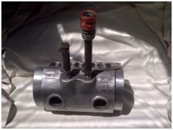 Fit some new 1½ brass welsh plugs to the water jackets. The original plugs were of the cup-type (albeit steel), which can be used. Used a smidgen of sealer around each plug and then tap the plugs in using a socket as a drift. 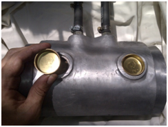 It is a good idea to pressure check the water jackets at this stage. The temporary steel 3/8NPT nipples and heater hose can be used to connect to tap water pressure. For a pressure gauge, you can use a low-cost tyre pressure gauge from SuperCheap/Repco (as per the image below). 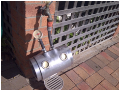 For those wanting a bit more accuracy (or where your tap pressure is not high enough) a hand pressure pump can also be used (the one in the photo below is a MityVac pressure/vacuum pump handy for pressure testing, but also for vacuum testing things like Stromberg power bypass pistons and automatic transmission vacuum modulators). 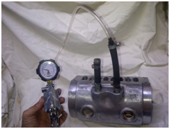 |
|
|
|
|
Logged
|
|
|
|
|
Harv
|
|
« Reply #129 on: March 22, 2014, 12:53:37 PM » |
0
|
My tap pressure is around the 15-20psi mark, though yours may be lower. Bear in mind that a Holden grey motor will only generate 7psi radiator pressure (controlled by the radiator cap), whilst the later red/blue/black motors can generate up to 14psi
this is why I like to test to 15psi. When testing the casing water jackets, fill the casing with water and vent out any air from a high point before fitting the pressure gauge. Crack the water tap and bring the pressure up slowly, looking for any weeping. Shut the water off and make sure it holds pressure for a few minutes. WARNING: whilst it is unlikely that the casing will give way, there is a moderate potential that the welsh plugs are ejected at high speed. Do not stand in front of the welsh plugs! A face shield is not a bad idea. Of note, Ive found that the 1½ brass cup-type welsh plugs (shown below on the right) do not seat very well on the Type 65 Normans (the alloy casing lands are quite shallow), and have a tendency to blow out at 15psi. I recommend instead that you fit 1½ cadmium plated steel dome-type plugs (shown below on the left). 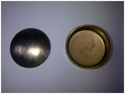 The dome-type plugs are tapped in with a ball-pein hammer and expand, holding them more securely than the cup type. Go easy on the tapping process a few light taps are better than thumping the hell out of the casing. 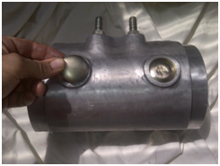 From most of the photos I have seen, the original Norman casings were either bare alloy (the earlier Eldred Normans like the Type 65) or purple anodized (the later Mike Normans). The early, early Eldred Normans did however have carnation-red end plates. Notwithstanding this, it remains common practice (and can look pretty cool) to paint in between the fins of the Type 65 Normans with red paint. If you are going to do this, now is a good time to do so. Clean the casing fin area up with some thinners or wax/grease remover and then mask up. A good engine enamel will suffice for this task, as normal paint will not usually handle the heat/fuel exposure. A good choice is Dupli-Colour Engine Enamel in Ford Red (DE1605), whilst the primer is Dupli-Colour Gray Engine Primer (DE1612), both available from SuperCheap Auto - typically one coat of primer, then three wet topcoats of red. In between wet coats (10 minute wait time as these are wet coats), wipe down the tops of the fins with a rag lightly covered in thinners. Once the paint had cured, do a final clean up of the tops of the fins with thinners. 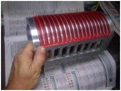 |
|
|
|
|
Logged
|
|
|
|
|
Harv
|
|
« Reply #130 on: March 22, 2014, 12:54:29 PM » |
0
|
Once the casing is painted, fit the brass 3/8NPT nipples to the water jackets. The nipples are handy as handles in some of the next few steps where the casing end plate bolts are torqued up. 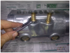 Note that NPT is a tapered thread which uses a metal-to-metal seal. There is no need to use Teflon tape or thread sealant on the threads unless they are badly damaged. Teflon tape and thread sealant are for straight (not tapered) thread
using them on tapered thread is the equivalent of using a pair of pliers to undo nuts. Its not a bad idea to use a flare nut spanner on the nipples, as the brass is quite soft. With the casing prepared, we can turn out focus onto the end-plates. Check the inside surfaces of both the drive end and non-drive end end-plates for gouges. It is quite common to find circular grooves either from the rotor shifting around and rubbing, or from something getting inside the casing (loose nut, bit of grit, busted vane spring etc). Grooves on the drive-end plate can also be caused by excessive rotor end thrust (say from misaligned pulleys). The grooves can act as a pathway for the compressed air/fuel mix, allowing leakage around the vanes and hence lower boost pressure. 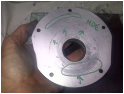 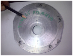 To remove the gouges, you can put the plates in a lathe and turn down the surface until they are flat. However, most home workshops (including mine ) dont have access to a lathe. A simple solution is to lap the gouges out. This is a little more labour intensive, but very much cheaper than purchasing a lathe. A lapping plate is made by purchasing a thick (~½) sheet of glass, a little bigger than a sheet of sandpaper (9x11). Glass plate of this size can often be got from your local glazier as an offcut mine cost $5. A couple of stick-on rubber legs from Bunnings will stop the plate sliding around, whilst two bulldog clips will hold the sheet of paper in place. 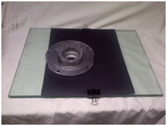 To lap out the gouges, start with course wet-and-dry paper (80 or 120 grit), and apply a little water to float out the particles from the paper surface. The end plate is then held down with gentle hand pressure, and rubbed across the paper in a figure-eight motion. Do not go backwards or forwards or in circles as this can cause grooving in the plate. Care needs to be taken to keep the pressure on the plate fairly even (i.e. not leaning forwards onto one side). Once a uniform surface finish has been made (rubbing out the marks), change the paper to a finer grade. Wash the end plate in water to remove any old grit, then go again with the finer paper. By moving successively through the finer grades of paper, a nice clean surface is obtained. I stopped at 400 paper, as there is no need for a mirror finish on this surface remember that the end plates have a moderate degree of porosity (see the image below). 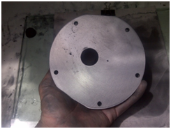 |
|
|
|
|
Logged
|
|
|
|
|
Harv
|
|
« Reply #131 on: March 22, 2014, 12:55:15 PM » |
0
|
Once the end plates gouges are removed, check inside the bearing mounting surfaces for any small burrs in the aluminum where the bearing had grabbed, either in installation or disassembly. These marks are not a major concern provided they do not impede the bearing from being reseated, and can be removed gently with a sharp file. 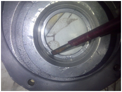 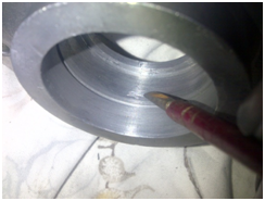 Finally, give the end plates a clean-up in some soapy water, rinse them off and air-blow dry. Protect the aluminum by giving the surface a quick cut and polish on the buffing wheel, again rinsing off afterwards. Time to put together out newly machined end plates. Starting with the drive-end end plate, lightly oil the inside of the bearing boss with some light machine oil. Tap in the new seal using a socket as a drift. Protect our nicely-flat end-plate face by doing this operation on a wooden surface padded out with some newspaper. 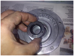 Take care to make sure the seal is fully (though gently!) seated, and square to the bore. Once installed, smeared some more light machine oil around the lip of the seal, ready to take the rotor shaft. Fit the new drive-end bearing, either with a press or by using a socket as a drift. Note that either the press plate or the socket should rest on the bearing outer race only not the inner race. 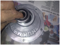 Note that this is a shielded (sealed) bearing, so no greasing is required. Take care that the bearing is fully seated, and square to the bore. |
|
|
|
|
Logged
|
|
|
|
|
Harv
|
|
« Reply #132 on: March 22, 2014, 12:56:21 PM » |
0
|
Lightly oil and then install the bearing snap ring, taking care that the snap ring is fully seated into the groove. This then completes the assembly of our drive-end end plate. 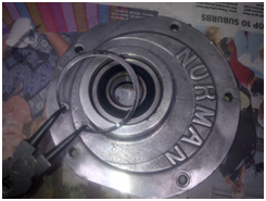 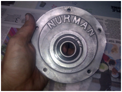 Use the assembled end-plate and casing to cut a drive end gasket. 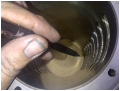 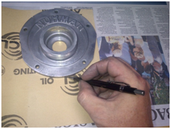 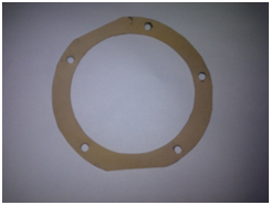 As a starting point, I use ACL Gasket Material Pack 04 to suit Oil Jointing, which is 0.4mm thick (SuperCheap Auto part number 765164). Whichever gasket material you use, make sure you record the thickness as it is important to setting the rotor end-float later in the assembly process. I did a similar gasket cutting a little later for the non-drive end plate gasket. Check the non-drive end plate for gouges or burrs, and lap/remove them as needs be. Polish, clean and dry the plate ready for assembly. Assemble the non-drive end plate by again lightly oiling the bearing boss, and then pressed in the bearing outer race. Note that the non-drive end bearing is a two piece unit, so the inner race is added separately. 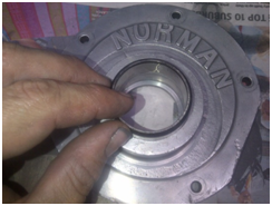 |
|
|
|
|
Logged
|
|
|
|
|
Harv
|
|
« Reply #133 on: March 22, 2014, 12:57:04 PM » |
0
|
Install the bearing snap ring, taking care that it was fully seated in its groove. 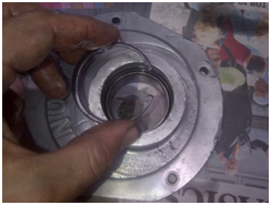 Trial fit the inner bearing race into the end-plate. 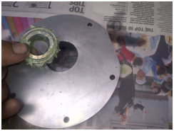 Note that the inner bearing race is free to move on the outer race, but an interference fit on the rotor shaft. This means that if you put the bearing into the end plate and try to push the rotor through, the rotor grabs the bearing inner race and separates the inner/outer races. The easier way is to install the bearing inner race onto the rotor, and then install the combined bearing inner race/rotor into the end plate. For the time being, store the inner race away. Note that the non-drive end bearing is not a sealed unit, and requires grease packing. In this case, I have used Shell Gadus S3 T100. This grease: a) is suitable for roller and ball bearings (pretty damn important given that is what it is going onto
some greases used for king pin and chassis greasing will not be suitable), b) is good for 160ºC (a high temperature range is important particularly if no water injection is used when we first get the unit going), c) can handle higher bearing speeds, d) is water tolerant (important if we are using water injection upstream of the supercharger), and e) has a long service life (important as Norman superchargers are not fitted with grease nipples). |
|
|
|
|
Logged
|
|
|
|
|
Harv
|
|
« Reply #134 on: March 22, 2014, 01:00:35 PM » |
0
|
After getting the end plates ready, prepare the rotor by giving it a clean-off in some kerosene, and then lightly oil with light machine oil. The drive-end end plate is then slipped over the rotor, taking care to be gentle with the lip seal. Note that the photograph shows the gasket and bolts in place temporarily. 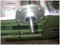 Assemble the thrust washer and key onto the rotor shaft, taking care with the orientation such that the stepped inner landing bears up against the drive end bearing inner race. 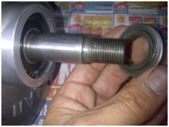 Install the drive pulley and pulley washer. Note that the pulley has again previously been given a light cut and polish on the buffing wheel, giving a nice shine, though not a mirror finish. 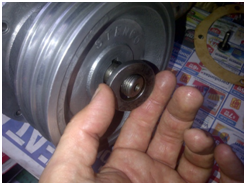 We now need to set the cold end-clearance between the rotor and casing at the drive end. As we have seen previously, this can be done in one of two ways: a) relying on the shaft nut to lock (nylock nut), or b) allowing the shaft nut to bottom out, and choosing an appropriately thick pulley washer to set the clearance. Personally, I prefer the latter. Whichever one you choose, we now need to install the shaft nut and tighten it. To tighten the assembly, I use a piece of steel flat bar (16x1¼x6.5mm) wedged into the rotor slot to hold the rotor still whilst torquing up the locknut (this piece of flatbar is a handy Norman tool... I can see it getting a fair bit of use in the future ). 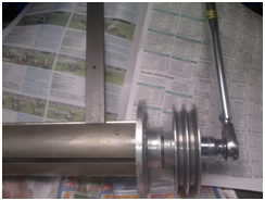 |
|
|
|
|
Logged
|
|
|
|
|
Harv
|
|
« Reply #135 on: March 22, 2014, 01:01:16 PM » |
0
|
This size nut could probably be torqued up to 150lb/ft when new. However, recognise that the thread on the rotor shaft is not in pristine condition, has a keyway cut through it, is not heavily loaded, and that if stripped would be a bugger of a repair. For this reason, I only torque the nut to 50 foot-pound. If you are choosing option a above (nut not bottomed out), then lightly tighten the nut. Once the assembly is torqued up, checked the clearance between the end plate and rotor using a pair of feeler gauges. 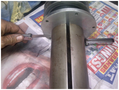 We are aiming for a clearance of 0.010-0.015, as used for Judson superchargers. Too little clearance and the rotor will bind/rub, too much clearance and the gas will not be pressurised. If using option a, adjust the shaft nut until you have the correct clearance. If using option b, select a thinner/thicker pulley washer to get the correct clearance - if the clearance it too big, install a thinner pulley washer (or skim down the existing one), and if the clearance is too small, install a thicker pulley washer or shim washer. Now that the drive end clearance appears we can set the non-drive end clearance. The end-clearance is a lot harder to check on this one, as the rotor floats through the bearing. This means that you cant assemble the unit and use feeler gauges like the drive end. Instead, a product called Plastigauge is used. Plastigauge is a little string/stick of material that looks similar to plasticine. It is of very accurate dimensions, with different grades of Plastigauge used to measure different clearances. 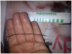 The Plastiguage is applied to the non-drive end of the rotor, as per the photograph below. 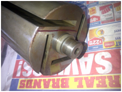 |
|
|
|
|
Logged
|
|
|
|
|
Harv
|
|
« Reply #136 on: March 22, 2014, 01:01:54 PM » |
0
|
We will then assemble the rotor, and squish the Plastigauge. As the Plastigauge is squished, it flattens out. The width of the squished Plastigauge then indicates the clearance. We then open up the casing again and read off the width of the squish using the little green indicator cards seen in the picture. Fit the non-drive end bearing onto the rotor, taking care to either press or drive it on squarely. 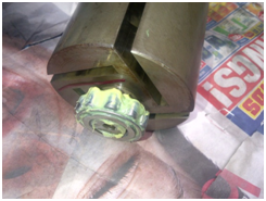 Assemble the rotor/drive end assembly into the casing, using the newly cut gasket. Tighten the end-plate bolts. For the Type 65 Norman, these are five ¼-28UNFx1 bolts, and should be torque to 50 inch-pounds (not foot-pounds!). This is not a very high torque, but bear in mind that the bolts are small, the threads lubricated and are into aluminum. The water jacket nipples are quite handy here to use as handles to stop the casing rotating whilst torqueing the bolts. The non-drive end end plate and gasket is then gently installed, taking care not to bump the Plastigague. The respective end-plate bolts (five ¼-28UNFx1 for the Type 65 Norman) are again torqued up to 50 inch-pounds, taking care not to turn the rotor as this is done. The bolts are then undone, and the non-drive end plate is then removed (gently), and the Plastigauge examined. As the Plastigauge has been squished, it flattens out. The width of the squished Plastigauge then indicates the clearance, and is read off using the little green indicator cards. In the image below the thickness is around 0.2mm, or 0.008. We are aiming for a clearance around 0.025 (as per Judson supercharger practice). 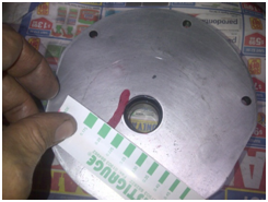 If the clearance is too large, thinner gaskets (either or both of the drive end and non-drive ends) can be used. If the clearance is too small, thicker gaskets can be used. Remember as my starting point I used 0.40mm (0.016) thick gasket paper for both the drive end and non-drive ends. This means we start with a total of 2 x 0.016 = 0.032 of gasket material to play with. We could change one gasket, or both gaskets if needs be to get the right thickness combination for our end float. Note that neither gasket will change the drive end clearance. Repco and SuperCheap sell gasket sheet only as thin as 0.4mm (as thick as 3.2mm), whilst CBC Bearings stock 0.3mm (0.012). To get thinner sheet try Blackwoods, whose stock both 0.15mm (0.006) and 0.25mm (0.010) as part numbers 05118683 and 05334302 respectively. Once we have the right gaskets selected, the vanes can be put into the rotor and the casing end plates (finally) buttoned up. Care should be taken that the vane grooves are on the counter-clockwise side of the rotor (as viewed from the drive end). In the image to the right, the grooves go where the green arrow is, not the red arrow. 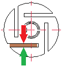 |
|
|
|
|
Logged
|
|
|
|
|
Harv
|
|
« Reply #137 on: March 22, 2014, 01:02:41 PM » |
0
|
As noted above, new Bakelite vanes can be sourced from Bearing Thermal Resources. When doing so, it is a good idea to specify the Bakelite as slightly oversized, and then machine it down to suit your specific rotor. Particularly, the width of the vane must be machined down such that it is only as wide as the rotor (remember that we only have about 10 thou of clearance either side to the casing). It can be quite difficult to file and then sand down these end surfaces to a fine finish, square and high tolerance. To assist, we can again use our lapping plate. The vane is held in a simple lapping jig, made from some aluminum angle iron (from Bunnings) and two bolts with wing nuts to clamp either side of the vane. 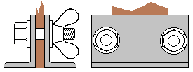 The vane is placed in the jig on a flat surface so that it is square with the bottom of the angle iron. As the vane is lapped, both the vane and the angle iron will be machined down. This slows down the lapping process, which is not a bad idea given how easy it is to machine the Bakelite (very easy to sand off a little too much). Once one end is square and finished (lapped down to about 400 grit paper), the rotor is removed from the clamp and compared to the rotor. The opposite end of the vane is then clamped in and lapped down to the right overall length. Note that new Bakelite vanes should be soaked in engine oil overnight before installing (reused vanes just need a light coating of light machine oil). With the casing buttoned up we can then tap in the non-drive end welsh plug (for the Type 65 Norman this is a 17/8 brass cup-type plug), using a socket as a drift to drive it in squarely. 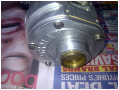 The plug provides a pressure seal for the non-drive end of the supercharger. When we get around to pressure testing the entire casing/manifold, we will need to check that this plug remains nicely seated. This pressure testing will be done with air, and will be done when we set the manifold relief valve (pop-off safety valve). The next item we will look at is the inlet manifold. The manifold for the Type 65 bolts to the top of the casing. Give the manifold a light cut and polish on the buffing wheel, and again clean it up in some soapy water before air blowing dry. Use the clean manifold to trace out the gasket required. 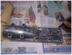 |
|
|
|
|
Logged
|
|
|
|
|
Harv
|
|
« Reply #138 on: March 22, 2014, 01:03:44 PM » |
0
|
Bear in mind that this is a large surface area, relative narrow and liable to be somewhat uneven
not a bad idea to use the thick 0.4mm gasket sheeting for this gasket to give plenty of take-up. The studs for the Type 65 inlet manifold are six ¼-28UNFx1¾, and four 5/16-18UNCx3 studs (present). If you need to get hold of new studs it can be quite difficult, especially the ¼-28UNF size. An easy way is to use some high tensile bolts with the heads cut off then dressed. 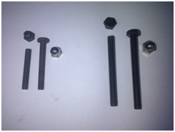 These should be matched up to acorn nuts for the period correct look. You can of course use plain bolts (as many early Normans do), though studs and nuts are a lot neater. The acorn nuts are available in stainless from Lee Brothers Engineering in Parramatta if you cant get them locally. Care needs to be taken when installing the studs if the cut the head off a bolt method is used. The casing holes are through to the water jacket (not blind), and hence it is possible to install the studs until they touch the cast iron liner. It is a good idea to install the studs so they are not touching the jacket, as the cast iron in contact with the high tensile steel will set up a galvanic cell, accelerating corrosion (it would be just my luck for the cast iron liner, not the stud, to corrode). Remember also that the acorn nuts only go on so far
. Its a good idea to trial fit the studs first to check they are the right length. Once all looks good, install the studs with some Loctite blue thread locker. This is needed as the studs do not bottom out and lock if the cut the head off a bolt method is used. If engineers studs are used, they will bottom out, and Loctite is not needed (use thread sealer instead). Once set, the gasket and manifold can be mounted to the supercharger. The ¼-28UNF studs can be torqued to 50 inch-pounds, whilst the 5/16-18UNC can be done up to 80 inch-pounds. As you can see from the images to the right, its now looking more like a Norman. 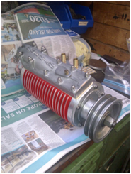 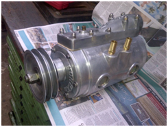 Cheers, Harv (deputy apprentice supercharger fiddler). |
|
|
|
|
Logged
|
|
|
|
|
Harv
|
|
« Reply #139 on: March 28, 2014, 02:29:30 PM » |
0
|
Ladies and Gents, A quick correction. In an earlier post (early October 2013), I reported that Weiand had found that for Rootes type superchargers, running 92 octane fuel, with no intercooling and with no ignition retard that pinging will not occur with an effective compression ratio lower than 12:1. 92 octane fuel seems a little low given that 98 is freely available in Australia. I had made a mistake however as petrol in Australia is sold by its Research Octane Number (RON), whilst American petrol (gasoline) is sold by the average of its RON and its Motor Octane Number (MON) i.e: Australian octane = RON American octane = (RON + MON)/2. RON and MON are similar, being just two different ways to measure when a fuel will ping. The upshot of this is that American octane numbers (for the same fuel) seem lower. As a rough guide, Australian 95 octane = American 91 octane Australian 98 octane = American 93 octane. If we then translate Weiands rule into Australian, they saw that for Rootes type superchargers, running 97 octane fuel, with no intercooling and with no ignition retard that pinging will not occur with an effective compression ratio lower than 12:1. That sounds more realistic. Note also that the chart I presented that brought together the Weiand and Miller/Bell/Bells experience was also incorrect, and was really in US octanes. Re-drawing the chart in Australian octanes: 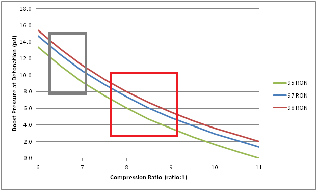 The grey box I have drawn on the graph indicates the range of compression ratios seen in factory Holden grey motors (6.5:1 to 7.25:1) whilst the red box indicates the same for EH-HR Holden red motors (7.7:1 to 9.2:1). The graph shows that for our grey motor running on 98 RON premium pump fuel we should be able to achieve 10-13psi of boost without pinging (and about 9-11psi if we run el-cheapo 95 octane). This is also more realistic. Apologies for the error. Cheers, Harv (deputy apprentice Norman supercharger fiddler). |
|
|
|
|
Logged
|
|
|
|
|


