FE-FC Holden Discussion Forum
April 30, 2024, 06:21:12 PM *
Welcome, Guest. Please login or register.

Login with username, password and session length
News: The FE-FC Holden Car Club of NSW are proud to host the 19th FE-FC Holden Nationals. Check out the announcement video for more.
 
   Home   Help Search Calendar Login Register  
Pages: 1 [2]   Go Down
  Add bookmark  |  Print  
Author Topic: 12V Bosch Generator - Exploded Diagram  (Read 6543 times)
Harv
Guru
*****
Offline Offline

Model: other Holden
Posts: 1319


View Profile
« Reply #20 on: November 22, 2023, 08:41:51 AM »
0

I'm kinda following the discussion on the generator test bench, but some is electrical sorcery (mostly the description of how the constant current loads are simulated with modern components).

Some time back I bought a generator test kit, and Rob kindly gave it a once-over. Does this box solve the test bench problem?

Happy to loan it out if it helps.

Cheers,
Harv
Logged
Jolls
nsw-club
Full Member
***
Offline Offline

Model: FC
Posts: 195


View Profile
« Reply #21 on: November 22, 2023, 09:29:09 AM »
0

Craig,

The generator test setup's three phase motor could do with more oomph, but you make do with what you can scrounge from work . . .

The other problem's got to do with switching transients in the dummy load.  I'm using low-dropout voltage regulators with booster transistors as constant-current loads.  All fine in theory, but the practice is a different matter.  The regulators can turn off way faster than the generator can react.  I had an FJ Bosch generator on full song, and turned the 20A load off.  There was a coughing sound, and the magic smoke came out.  The field current had to decay somehow, and it did so by generating a huge voltage spike, which took out the lower-current sections of the dummy load, and the cooling fan.

I've thought up a soft-start and -stop system, but it'll use a voltage reference and op-amp instead.  Still to be implemented.

And don't admit that you've had experience at rewinding DC machine armatures.  I have a couple of 6V Delco generators needing armature rewinds . . .

Rob

Hi Rob

Had a think about setting up a test rig similar to what is shown in the manual. The setup in the manual has a few features that aren't required to do the testing required if set up to test generator/regulators on and off the vehicle and may be a simple solution to the smoke issue. Given the smarts out there a fan could be added cheaply that can handle 6-24V so the test rig itself could be used on old style 6-24V generator/regulator setups. This is the solution I have in mind:


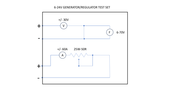
Interested if you think this soulution would overcome the problem - something I intend to knock up for the shed so I can test. I will build a prototype and test it out then see what I can fabricate in an old style wooden boz with a bit of stainless for character.

For driving the bench test setup I am in the same boat and have a couple of three phase motors sitting around. Definitely need a viable speed drive to simulate RPM variations for bench testing. I will try lay my hands on a single phase motor as the ones I have are quite heavy. I use a capacitar start system to get them running on single phase and a drive to regulate the RPM.

As for rewinding armatures; it is either winding by hand, which is tedious or potentially adapting a manual coil winding machine by adding an arm to guide the wire around the armature slug to spin (and count) the winding number. I think the key to this is being able to hold the armature vertically and secure it while it is being wound. A jig for the field windings could be made for a few scraps of timber but a tow piece aluminium casting would be sweet as it would be very easy to get the windings off the jig. Once the jig(s) is/are built it then becomes finding a source of new commutators, wire and finding some time to do the work. 

 have a heap old pistons that are dying to be melted down into something useful; and I expect I now have a plan for them. I just need to retire so I can get cracking on it; only a few more years! In the meantime I will find a couple of dead gennys to "experiment" on.

Cheers n Beers
Jolls
Logged

Cheers n Beers

Jolls
Jolls
nsw-club
Full Member
***
Offline Offline

Model: FC
Posts: 195


View Profile
« Reply #22 on: November 22, 2023, 09:48:43 AM »
0

I'm kinda following the discussion on the generator test bench, but some is electrical sorcery (mostly the description of how the constant current loads are simulated with modern components).

Some time back I bought a generator test kit, and Rob kindly gave it a once-over. Does this box solve the test bench problem?

Happy to loan it out if it helps.

Cheers,
Harv

Hi Harv,

You must have posted this while I was posting my reply as I missed it.  I expect that is does - the modern electrickery really tries to emulate what was done with wire wound stuff in the day.

If I have interpreted it correctly I think what Rob has experienced is that the modern equivalent jumps instantaneously from load A to load B at the flick of a switch and the immediate collapse/increase in current a second order effect that we are not faced when the current is turned down by hand in a wire wound rheostat. I think this is what he was referncing in relation ot soft start/stop systems. I have a baisc understanding of the digital electrical world but have learnt it all post my formal training. I have a pretty good understanding of the DC principle and how the older systems work.

The bench test issues, are more about replicating engine RPM on a single phase supply with a three phase motor and how to protect the digital and ancillary componentry. This motor can be overcome with an off the shelf solution and tricking the motor to think it has a three phase supply on start up. Once it is running it just does its thing. The latter is a more complex issue that is beyond my electronic skills; however, the generator test kit was used as the primary tool for GMH in 1959 so it will definitely work now.

Cheers
Jolls
Logged

Cheers n Beers

Jolls
ardiesse
nsw-club
Guru
*****
Offline Offline

Model: FC
Posts: 1288


View Profile
« Reply #23 on: November 22, 2023, 10:27:23 AM »
0

Craig,

Your power rheostat setup is essentially what GM recommended.  It goes in series with the load (if I understand right).  And for the load, the manual suggested making up a lamp bank with switches.  The ammeter is needed to measure the current.

Using constant-current loads allowed me to do away with the ammeter, but at the cost of less-than-ideal behaviour when turning off the high-current loads.

Rob
Logged

Remember: if your Holden's not leaking oil, it doesn't have any.
Jolls
nsw-club
Full Member
***
Offline Offline

Model: FC
Posts: 195


View Profile
« Reply #24 on: November 22, 2023, 12:07:48 PM »
0


I'm kinda following the discussion on the generator test bench, but some is electrical sorcery (mostly the description of how the constant current loads are simulated with modern components).

Some time back I bought a generator test kit, and Rob kindly gave it a once-over. Does this box solve the test bench problem?

Happy to loan it out if it helps.

Cheers,
Harv

Hi Harv,

It would be great to see a pic of the internals, for wiring and any components for markings as they had all he data to build what they did. I'm sorta guesstimating a solution at the moment.

Cheers
Craig
Logged

Cheers n Beers

Jolls
Jolls
nsw-club
Full Member
***
Offline Offline

Model: FC
Posts: 195


View Profile
« Reply #25 on: November 24, 2023, 12:57:44 PM »
0

Hi All,

I've had more of a think on the test rig - ammeter and voltmeter no problems but I'm pretty sure I over simplified and theroefore over specified the rheostat requirement. My simplified circuit did not consider the internal resistance of the battery, the resistance of the circuit or any other factors. I'm also not an auto sparky so my theoretical approach may not on the money either. If someone is out there with a better understanding feel free to jump in and point me in the right direction. Your insights and support would be greatly appreciated.

Internal battery resistance in a good battery is around 500 mOhms so I used that figure as a constant to work with. I also know that the endstate of the most challenging test is to bring the charging system up to 8-10 Amps at around 13.4V (134 Watts). The generator is rated at 20A and 240W @ 12V so no problems there.

My start point is: a fully charged battery in a prefect world with an internal resistance of 0.5 Ohms. In this state the generator would probably be producing 12.5V and only consuming around 40W to trickle charge the battery. This current flow would be around 3 Amps I expect.

That means, to increase the current to the required 8-10A we need to increase the resistance.

As the resistances are in series and the internal reisistance of the battery is known (estimated) the worst case resistance would be the resistance required to create and 8A load at 13.4V (1.675 Ohms) less the battery internal resistance (0.5 Ohm). This is an additional 1.75 Ohm resistance to achieve an 8 Amp load or 0.84A to produce a 10A load. Power wise this would require a rheostat rated to 75 -85 Watts.

So much for theory, in practice I expect things would be much less as I have not taken into account the resistance already in the system as a result of joints and cabling etc. so the base current load would be slightly higher.  I also expect that the battery would not be fully charged etc.

I do have a 25W 300 Ohm potentiometer laying about that I expect I could use if I did some fancy work to build a suitable shunt (protections). I decided to keep that as a backup plan for if I let the smoke out.  So I have ordered in a 100W 5 Ohm rheostat, a +/- 15V Voltmeter and a +/-50A Ammeter. I ditched the idea of the fan as they didn't require them in the day so if it worked then it will work now.

I will start on the rest of the test setup while I wait for the parts to arrive. I am thinking of using my lathe to drive the generator for the prototype as I can simply support it and place the armature shaft in the chack and use a 1:1 drive. If the smoke stays in and I can replicate the test scenarios I will look to build a dedicated bench with a mobile test box so I can test on car as well as at the bench.

Let the fun begin.
Logged

Cheers n Beers

Jolls
Harv
Guru
*****
Offline Offline

Model: other Holden
Posts: 1319


View Profile
« Reply #26 on: November 26, 2023, 03:56:13 PM »
0

It would be great to see a pic of the internals, for wiring and any components for markings as they had all he data to build what they did. I'm sorta guesstimating a solution at the moment.


Cheers,
Harv
Logged
Jolls
nsw-club
Full Member
***
Offline Offline

Model: FC
Posts: 195


View Profile
« Reply #27 on: November 26, 2023, 08:13:48 PM »
0

Thanks @Harv,

That is gold. Thank you so much for taking thos photos. I just love simplicity!

Pretty much as per the design above with the exception of using dual scale meters and shunts to protect the meters from over-current.

I have opted for full scale meters as I couldn't find a cheap dual scale meter on AliExpress, I guess I will find out if that is a design flaw scale wise.

That is a hell of a wire wound rheostat. I trust I have the calcs right and a 100W is suitable. Could you possibly check the resistance between the negative and positive leads to the rheostat with the dial set at in and out? That should give us all the info we need to purchase a suitable clone.

As an aside I had a good chat with an auto sparky over a few beers last night. He had no idea as to how to calculate the rheostat and never in his life had he had any requirement to know the internal resistance of a battery. His approach was... "don't overcomplicate things - run it as a motor - if it works it is good! Then throw it on the car, if it ran as a motor it will run as a generator. Then check the output and adjust the regulator."

When I asked what to do if it wasn't up to speed his response was - throw it out and get a new one.

At the end of the conversation he asked if he could come over and see how it is done - he is really interested to learn the process and see the "witchcraft" as he called it!

I expect that it wasn't such a throw away society in the 60s so they did a lot more in house diagnosis and repair before opting to replace.

So to answer your earlier question about the bench test solution the meter(s) you have there is definitely more than 50% of the requirement. All you need now is an ability to drive the generator at 1500 to 2400 rpm on the bench. A variable drive is the way to go so you can see how the generator operates through its full range. However, if you aren't doing it often the grey motor in the car is a perfect drive and all of the tests can be done with the test box.

Cheers n Beers
Jolls

Logged

Cheers n Beers

Jolls
Harv
Guru
*****
Offline Offline

Model: other Holden
Posts: 1319


View Profile
« Reply #28 on: November 27, 2023, 12:20:25 PM »
0

Could you possibly check the resistance between the negative and positive leads to the rheostat with the dial set at in and out?

Fifteen (15) ohms. Measured at one terminal (as it is nice and clean and a robust fitment) and at the carbon brush (as the little wire that leads from there to the gauge is manky and fragile).

Cheers,
Harv
Logged
Jolls
nsw-club
Full Member
***
Offline Offline

Model: FC
Posts: 195


View Profile
« Reply #29 on: November 27, 2023, 03:12:18 PM »
0

Thanks Harv,

I have selected a rheostat at 1/3 that rating so hopefully I don't need the additional resistance to keep the current down. I guess time will tell!

Really appreciate the photos and the support.

Where did you manage to find the original meter set? A great find!

Cheers
Craig
Logged

Cheers n Beers

Jolls
Harv
Guru
*****
Offline Offline

Model: other Holden
Posts: 1319


View Profile
« Reply #30 on: November 27, 2023, 04:39:23 PM »
0

EBay I think. The seller was unsure what it did.

Cheers,
Harv
Logged
Pages: 1 [2]   Go Up
  Add bookmark  |  Print  

Share this topic...
In a forum (BBCode) 
In a site/blog (HTML)

 
Jump to:  

Powered by MySQL Powered by PHP Powered by SMF 1.1.21 | SMF © 2015, Simple Machines Valid XHTML 1.0! Valid CSS!
Page created in 0.044 seconds with 20 queries.