|
Harv
|
 |
« Reply #80 on: November 28, 2013, 12:08:28 PM » |
0
|
Seals are used in the Norman supercharger for two purposes. Firstly (and more obviously), the seals are to close the gap between the rotating shaft and the static casing to keep the boost pressure within the supercharger. In this case a poor seal means loss of boost pressure, and also a leak of (explosive!) air/fuel mixture into the engine bay. The second reason for the use of seals is more subtle. Under low load conditions (low speed), the supercharger and inlet manifold can come under vacuum, just like a normal (naturally aspirated) engine. In these conditions, a poor seal can lead to air ingress and unstable fuel/air mixtures. The drive-end seal of the Norman superchargers are twin lip seals with a garter spring. Dimensions of the seals are shown in the table below: 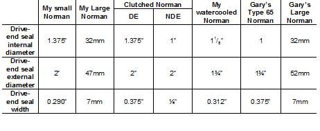 Many of the original Norman seals were of leather and/or felt construction
somewhat hard to find now. A suitable replacement is Nitrile Butadiene Rubber (NBR), which has a maximum temperature of 125°C continuous. Whilst Viton (225°C) would be a better chose, it is a lot less commonly available. In addition to NBRs temperature limits, NBR (like all materials) has a speed limit. Most seal manufacturers rate the speed limit using surface feet per minute (or meters per second). This is a measurement of how many surface feet meters) pass a given point at the seal lip per minute (second) in time. Since this method considers the shaft diameter in addition to speed, it is a better service indicator than RPM alone. A typical seal design in NBR material can operate up to 3,000 fpm (15 m/s) assuming all other operating parameters are reasonable. For Norman supercharger shaft diameters (1-1.4 diameter) this implies a speed limit of around 8500rpm (Timkin suggests this could be a little lower at 6500rpm for their TC seals). This speed limit should not be an issue given that most Norman superchargers will run at speeds similar to that of the crankshaft (~4500rpm maximum). Most seals that I pulled out of the Norman superchargers are simple TC profile type seals. TC seals are typically rated for 5psi operation. Whilst 5psi is in the typical Norman supercharger range, 10psi is not out of the question. There are better seal profiles available (for example Parkers LFN, LFE-S and MP seal profiles, as they are suitable up to 60psi). Note however that again availability may be an issue for these seal profiles I have not yet been able to find a decent seal profile in the sizes required for Norman superchargersother than the simple TC seals. For interest, LFN, LFE-S, MP and TC seal profiles are shown (from left to right) in the image above. 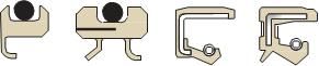 Cheers, Harv (deputy apprentice Norman supercharger fiddler) |
|
|
|
|
 Logged
|
|
|
|
|
Harv
|
|
« Reply #81 on: December 02, 2013, 10:54:32 AM » |
0
|
As promised, I want to return back to discussing SU carbs. In this post I am going to deal with a significant issue - try to obtain mixture control with monster carbs. It is possible, and fairly common, to run a single SU carburettor to feed a Norman supercharger (the 3 Norman SU is pretty rare, but a single 2 is run-of-the-mill). However, large single SU carburettors on supercharged engines can lead to a mixture spread issue. At full throttle, the supercharger is producing boost, squeezing in lots of air and lots of fuel. This requires a fairly rich needle profile. At part throttle however boost is very low (in some cases vacuum exists in the inlet manifold), and the engine behaves more like a naturally aspirated car. This then requires a normally lean needle profile. Whilst the full-throttle mixture can be tuned by finding an appropriate needle, the part throttle mixture may end up being overly rich (almost the same as full-throttle) leading to poor fuel efficiency. Whilst this issue is not too serious in race vehicles that always run full-throttle, it can be annoying in a road vehicle (poor economy and plug fouling). Finding a better needle profile may help solve the issue, though few needles are available for supercharged applications. One method to get around the mixture spread issue is to use the Additional Weakening Device, which was a fitting originally used in some SU installations (eg the HIF38S, also known as the metric HIF4). I will draw below on some information from both Tuning British Leylands A-Series Engine by David Vizard and Tuning SU Carburettors by Speedsport Motorbooks. The images below show the weakening device as installed to original SU float bowls: 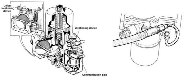 |
|
|
|
|
Logged
|
|
|
|
|
Harv
|
|
« Reply #82 on: December 02, 2013, 10:55:23 AM » |
0
|
The amount of fuel delivered by an SU main jet is governed, not only by the profile of the needle presented to the airstream, but also by the height of the fuel in the jet. In simple terms, if the fuel height is lower in the jet, it is harder for the carb to suck out the fuel, leading to a leaner mixture. The Additional Weakening Device works (leans the mixture) by lowering the fuel level in the jet. It does this by changing the pressure differential between the end of the jet (the carb throat) and the fuel in the float bowl. Normally the fuel in the float bowl is subjected to standard air pressure, as the float bowl is vented as per the image below:  . The height of fuel in the jet is then determined by the corresponding height of fuel in the float bowl (hydrostatic head, just like a water level gauge used by carpenters). The Additional Weakening Device however applies a partial vacuum to the top of the float bowl, as per the image below: 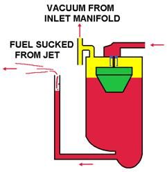 . The float still controls the float bowl level at the same height, giving the same hydrostatic head to the jet. However, the vacuum above the float chamber fuel level means that the total pressure seen by the jet is lower, and hence the fuel level in the jet drops down. By controlling how much vacuum is applied to the float bowl, different fuel levels in the jet can be made, and hence different mixtures. The Additional Weakening Device consists of a drilling in the carburettor throat (labelled 5 in the image below) which is connected by a flexible pipe to the top of the float bowl. 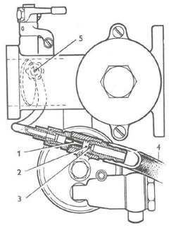 The drilling in the carburettor throat is made on the upstream side of the throttle butterfly (i.e. it supplies ported vacuum, not manifold vacuum). At the top of the float bowl a venturi (labelled as 1) is used to draw vacuum from the float bowl via a drilling (labelled as 2). The float bowl is sealed, with a vent line provided to let air into the bowl (labelled as 4). As this air is being sucked (through the float bowl) to the carburettor throat, the vent line is normally connected to the air filter to provide clean air. The amount of air that can flow through the vent line is controlled by an air bleed restriction (labelled as 3). The size of the venturi (1) is standard. The air bleed restriction diameter (3) is varied on different vehicles to determine the amount of vacuum applied (and hence the mixture strength). Note that the diameter and length of the flexible vent line (4) connecting the air bleed restriction to the air filter has a substantial effect on mixture strength. |
|
|
|
|
Logged
|
|
|
|
|
Harv
|
|
« Reply #83 on: December 02, 2013, 10:55:58 AM » |
0
|
With the throttle in the normal idling position (as shown in the image to the right), the drilling in the carburettor body is located upstream of the throttle butterfly, and is not able to see manifold vacuum: 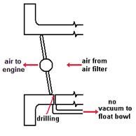 There is a very slight vacuum, but the effect on the float chamber will be negligible. This means that the Additional Weakening Device has no effect on the fuel mixture at idle. When the throttle is partly open (as per the image below), the drilling in the carburettor body becomes exposed to manifold vacuum: 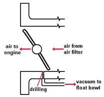 This causes air to be drawn from the float bowl via the venturi. The use of a venturi (instead of a plain orifice) ensures that the air velocity will reach a maximum value which remains constant. The air bleed on top of the float bowl allows air into the float bowl, though the flow is restricted by the air bleed restriction. This gives vacuum in the float bowl, causing the fuel level in the jet to drop and the mixture to run leaner. This arrangement allows the maximum fuel mixturing weakening effect to be produced when the throttle buterfly is closed a small amount from the full open position (when only a slight vacuum is present) and ensures that further closing of the throttle does not increase the weakening effect to the point at which misfiring may occur. When the throttle is fully open (as per the image below), manifold vacuum decreases to a very small amount: 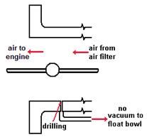 This small vacuum is able to act on the throttle body drilling, but is not sufficient to cause significant vacuum in the fuel bowl. In this way the Additional Weakening Device is not able to affect the mixture under full throttle operation. |
|
|
|
|
Logged
|
|
|
|
|
Harv
|
|
« Reply #84 on: December 02, 2013, 10:56:30 AM » |
0
|
Whilst a fairly simple piece of kit, the Additional Weakening Device consists of the fine air bleed restriction and the venturi. Both of these items have been tuned to a particular needle, jet and vacuum combination, and are not adjustable. If a factory Additional Weakening Device is used on a Norman supercharged vehicle, it may not behave as intended there is a risk of lean-out and resulting knocking (pinging). It is however possible to build a fully adjustable Additional Weakening Device from scratch. The scratch-built device has the same configuration as the factory Additional Weakening Device, as shown in the image below: 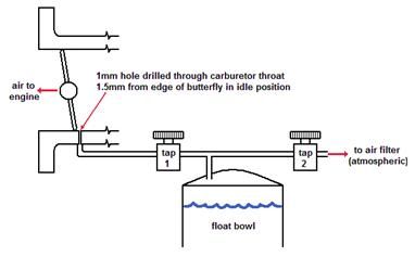 However, both the venturi and the air bleed restriction are replaced with simple needle valves (taps). This allows the amount of vacuum applied to the float bowl to be readily tuned by either restricting the air flowing in, or the vacuum pulling air out of the bowl. In building the system, it is important to have a running supercharger with the idle pretty much set. This allows the throttle plate position at idle to be determined. A hole is then drilled 1½mm (~0.06) from the edge of the butterfly in the relevant (upstream) side of the carburettor body. Remember, when the butterfly opens the hole must be in such a position that the butterfly will sweep over it, effectively moving it from upstream of the butterfly to downstream so that it communicates vacuum to the system. If the idle had not been set first, there is a chance that the hole ends up on the wrong side of the throttle plate. Suitable adaptors are then used to connect the carburettor body hole via vacuum hose to Tap 1. The taps need to be fuel resistant and able to pass a reasonable amount of air (you should be able to blow through it relatively easily when its fully open) brass air compressor fittings are not a bad choice. Tap 1 is then connected to the top of the fuel bowl, again using vacuum hose. The fuel bowl needs to be sealed, with the vent of the fuel bowl connected to Tap 2. The other side of Tap 2 is then fitted into the air cleaner. During tuning of the device, its handy to mount Tap 2 inside the car via a fairly long length of vacuum hose, with the other end looping back into the air filter. This hose can then be shortening back once the tuning is complete. |
|
|
|
|
Logged
|
|
|
|
|
Harv
|
|
« Reply #85 on: December 02, 2013, 10:58:01 AM » |
0
|
Care needs to be taken in tuning the system. Adjusting Tap 1 will change the rate at which the air is drawn out of the float bowl, whilst adjusting Tap 2 changes the rate that air can flow in to the float bowl. The balance of the two adjustments determines the vacuum inside the float bowl, and hence the mixture setting at part-throttle. lf too big a vent is used, the air will flow back into the float bowl as fast as it is being evacuated, cancelling out the effect we are trying to achieve. On the other hand if it's too small, then the vacuum created in the float bowl will be sufficient to totally stop the fuel going into the engine, causing the engine to stall when the throttle is opened.
To tune the Additional Weakening Device:
a) Establish just how much Tap 2 needs to be open. We want Tap 2 to be controlling the air flow to the float bowl, but not strangling it to the point that the a vacuum develops in the float bowl (and the mixture changes) under full load. To do this, close Tap 1 so that no vacuum is communicated to the float bowl. Set Tap 2 fully open so that the float bowl is adequately vented. Drive the vehicle and check the third gear 30-60mph flat-out acceleration time. To do this, it's best to start below 30mph and have an offside start the stopwatch as the speedo passes 30mph. Hit it again when it reaches 60mph, but always drive on past that speed by a few mph.
b) When you are sure the 30-60mph acceleration times are consistent, close Tap 2 slightly and do the test again. We are looking for the point where Tap 2 begins to control the air flow to the float bowl by strangling it to the point that the a vacuum develops in the float bowl (and the mixture changes). Continue repeating the test (closing Tap 2 a little more each time) until you find the point at which the 30-60mph acceleration times starts to deteriorate. ln some instances you may find that Tap 2 can go all the way closed without affecting the performance, in which case open Tap 2 about two full turns. Once you find the point that the performance starts to deteriorate, open Tap 2 slightly to restore the engine's performance.
c) Open Tap 1 very slightly and check that the engine picks up properly. Take the car out on the road and drive at your most used cruising speeds. These may range from your in-town cruising speed of around 35mph (55km/h) up to freeway cruising speeds of 70mph (110km/h). If you have a vacuum gauge, note the vacuum at each speed you test at (the road should be dead flat if using a vacuum gauge). What you are looking for is the engine beginning to run lean and surge. This is the same thing that the standard FB/EK Holden motor will do if the main metering jet is too small. When lean surge starts, the car becomes slightly hesitant, and can begin to lightly miss.
d) lf the car is not surging, open Tap 1 a little bit more, making the fuel further small increment. Take the car out and try it again. Continue repeating the test (opening Tap 1 a little more each time) until you feel the car run into lean surge under cruise. When this happens, close Tap 1 slightly so that the lean surge just disappears.
e) Now re-check your 30-60mph acceleration time. The acceleration time should not have changed from those achieved originally. lf it has changed, it's because there is a slight reduction in mixture strength at full throttle. The Additional Weakening Device does not change the mixture under full throttle conditions. However, if the engine is under-carburretted, the engine may pull fuel from the float chamber fast enough to overtake the air supply back into the float chamber via Tap 2. lf this is the case, you will have to compensate for this effect by one of two means, either increase the richness of the mixture by having a slightly slimmer needle at the top end, or sacrifice some of the potential weakening effect by opening Tap 2 slightly wider.
f) Remember that in playing around with mixture strengths there is a chance that the engine runs lean. It is a good idea to keep an eye on the spark plug readings for any signs of running overly lean until you are confident the mixture is right.
Note that the above process has been set-up for simple testing. It is equally possible to tune the Additional Weakening Device on a dyno by setting Tap 2 to peak power then adjusting Tap 1 for a good mixture quality (by exhaust gas analysis) under cruise conditions.
Cheers,
Harv (deputy apprentice Norman supercharger fiddler).
|
|
|
|
|
Logged
|
|
|
|
|
Harv
|
|
« Reply #86 on: December 05, 2013, 12:42:24 PM » |
0
|
For this post I will continue on with some info on SU carbs, focussing on the float bowl capacity.
There is no doubt that adding 50-100% more horsepower will increase the fuel demand on a vehicle. The typical full-throttle engine fuel requirement is 0.5lb per horsepower per hour, which equates to 0.0833 gallons of petrol per hour per horsepower. Our Norman supercharged grey motor is likely to achieve a 50-100% increase in power, giving 110-150 horsepower. The fuel requirement is thus likely to be of the order of 8-12gph on pump fuel. Eldred flags within Supercharge! that feeding the vehicle can become a constraint, both via the fuel pump (which I will deal with separately) and via the carburetor float bowl. Most road-going Norman supercharged applications running on petrol will be unlikely to hit this limit, as the standard SU needle and seat will flow of the order of 15gph. A single (2) SU needle and seat is thus likely to cope, and if we are running twin (1¾) SUs we should have absolutely no issue. Note though that for red motors our horsepower may increase to double that shown above. This would mean that even twin SUs become marginal for red motor petrol flow. Regardless of what motor we are running, the issue above becomes increasingly important if running methanol (bear in mind that you need to flow 2-2½ times as much methanol as petrol)
a methanol slurping grey will be marginal with two standard SU float bowls, whilst a red motor meth monster will still be hungry being fed by four.
|
|
|
|
|
Logged
|
|
|
|
|
Harv
|
|
« Reply #87 on: December 05, 2013, 12:43:09 PM » |
0
|
The carburetor float bowl is generally constrained by the size (diameter) of the fuel inlet needle and seat. A typical SU aftermarket (viton-tipped) needle and seat has a diameter of 0.090. One improvement made since Eldreds time is the availability of Grose jets (another type of needle and seat) for SUs. A Grose Jet is not a needle, but instead consists of two ball bearings in a solid brass cage, one large one that is moved by the float, and a smaller one that is moved by the bigger ball bearing until it shuts off the flow of fuel. The original reasoning behind the Grose Jets' design was to lower the liklihood that they would jam or stick (the original brass-tipped needless were reknowned for jamming - a lot less of a problem with modern viton tips). Grose-Jet inlet valves are available with orifices of 0.084", 0.099 and 0.125 diameters. As a comparison, Holley needle-and-seat assemblies are typically 0.097-0.150 diameter, whilst single-barrel Stromberg needle and seats ranged from 0.07-0.093 for Holdens (the aftermarket ones now available are typically 0.076 diameter). Note however that along with the diameter of the needle and seat, the fuel inlet pressure has a part to play. SU carburettors are happy to run on 1½-3½ psi, and overflow around 5 psi. Holley carburettors run happily at 5-7psi, whilst Stromberg carburettors operate on approximately 2½-4½ psi of fuel inlet pressure. Fuel flow is proportional to the square of the orifice diameter (i.e. flow α diameter2), and to the square root of inlet pressure (i.e. flow α√pressure). Calculating this through shows that a typical SU fuel bowl and standard needle and seat will have flow doubled if changing out to a Grose valve. The Grose-valved SU will flow nearly three times as much as a single-barrel Stromberg, but only two-thirds as much as a Holley i.e: 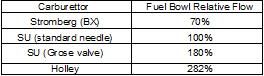 |
|
|
|
|
Logged
|
|
|
|
|
Harv
|
|
« Reply #88 on: December 05, 2013, 12:43:59 PM » |
0
|
The upshot of this is that if the standard SU float bowl is constraining the vehicle, changing to a Grose valve may solve the problem. If fuel flow is still constrained, the use of Holley float bowls (on SU carbs) may help. This sounds a little off-centre, but is exactly the solution implemented on the Norman supercharged 1963 Lil Horny Devil slingshot rail currently owned by Chris Batey: 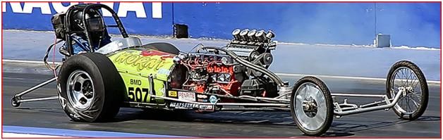 http://www.youtube.com/watch?v=4mLzZfjMamY http://www.youtube.com/watch?v=pWrMQfr8Zr8 http://www.youtube.com/watch?v=4mLzZfjMamY http://www.youtube.com/watch?v=pWrMQfr8Zr8 The Holley float bowl and associated parts are readily available and relatively cheap. The float bowl can be bolted to a piece of flat steel plate to form the rear of the bowl, as can be seen in the image below: 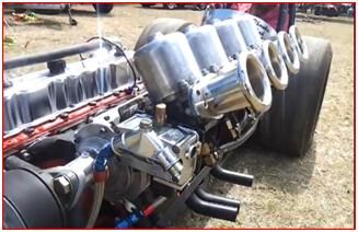 The original Holley mounting screws and gasket can be utilized. Note that Chris setup has two float bowls installed, one at either end of the inlet manifold (see photo below
the second bowl can be seen just sticking out from under the right-hand SU inlet trumpet): 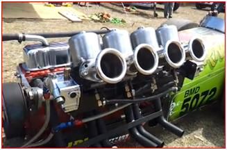 Care needs to be taken in locating the Holley float bowl at an appropriate height relative to the SU carburetor jet, as the fuel bowl level affects the height of the fuel in the jet, and hence the mixture strength. The diagram below shows how the bowl may be constructed: 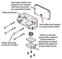 Note that for the outlet it is possible to drill and tap a hole into the back of the steel plate to accept a nozzle. In this case the accelerator pump assembly is retained to seal the bottom of the fuel bowl. Alternatively, fuel can be taken from the bottom of the accelerator pump assembly by removing the diaphragm, spring and pump arm and then tapping bottom of the float bowl to accept a nozzle. Note that the accelerator pump check ball and retainer strap, as shown in the photograph below should also be removed and the hole drilled out to remove the potential restriction: 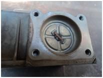 |
|
|
|
|
Logged
|
|
|
|
|
Harv
|
|
« Reply #89 on: December 05, 2013, 12:44:41 PM » |
0
|
For all-out race vehicles which wish to retain the SU carburettors, Eldred describes a modification to the SU float bowl which makes is operate as a weir fueled by a large capacity fuel pump. The weir is simply a hole drilled in the side of the float bowl at the desired fuel level. The standard SU float bowl operates as shown in the image below: 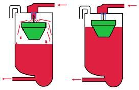 The float (shown in green) sits on top of the fuel level. As the fuel level drops (as per the left-hand image) the float drops with it, lowering and opening the needle valve. As the fuel valve rises to the desired level (as shown in the right hand image) the float rises, pushing u the needle and closing off fuel flow to the bowl. In Eldreds weir modification, the float is fully removed, as per the image below: 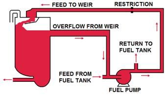 The fuel pump is able to freely supply fuel to the bowl at all times. Any fuel that the engine does not consume gets recycled back to the fuel tank. A restriction is placed into the feed line to the float bowl to stop the fuel flow from being excessive (and hence overflowing the float bowl). Provided the fuel pump has a high enough capacity, the fuel bowl level will never drop any lower than the weir overflow level. Whilst this system has more plumbing than the standard needle and seat, it is very resistant to the issue of jamming or plugging of the needle orifice. Cheers, Harv (deputy apprentice Norman supercharger fiddler). |
|
|
|
|
Logged
|
|
|
|
|
Harv
|
|
« Reply #90 on: January 18, 2014, 07:19:08 PM » |
0
|
OK, a quick post to whet your appetite again (everyone loves a FED... and especially a Norman-blown FED... and Harv really loves an injected Norman-blown FED  :lol: ). This one is Chris Stevensons front-engined dragster:  Photo above from the Street Machine Hot Rod Annual 2009. 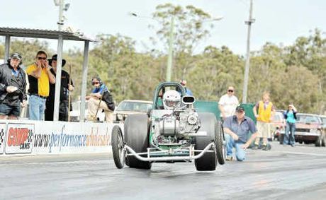   Original website for the two photos above is here: http://www.dragnews.com.au/index.php/feature-articles/race-reports/16-willowbank/737-eighth-mile-attackApparantly the 2008 Street Machine Hot Rod Annual has a feature on Chris' car - would love to get my hands on a copy or scan if anyone has one please. Cheers, Harv (deputy apprentice Norman supercharger fiddler) |
|
|
|
|
Logged
|
|
|
|
|
Harv
|
|
« Reply #91 on: January 19, 2014, 12:21:35 PM » |
0
|
Having whetted your appetite with the slingshot rail above, I'll return back to the earlier discussion on fuelling the Norman. Earlier posts centred on carbs, this post will look at fuel quality.
One of the downsides to the sliding vane supercharger is that the vanes rub against the casing wall. This creates friction and some additional heat, and is also a source of some efficiency loss. Over time, the vanes wear down and must be replaced. If the vanes get too short they can cant sideways in the rotor and jam. This can lead to bending of the rotor shaft or snapping of the rotor. To reduce the friction, a lubricant is required.
Historically, straight engine oil was added to the fuel tank, with the resultant two-stroke mixture used to feed the engine via the supercharger. The oil was dosed between 1 pint of oil:7 gallons of fuel (56:1 as recommended in Supercharge!) and 1 pint of oil: 8.7 gallons of fuel (70:1 as recommended in an advertising brochure for the later (Mike) Norman superchargers). One issue associated with the 2-stroke approach is that the resultant fuel can cause the carburettor to gum up over time. Note that some superchargers, notably the Judson, use an oiler that feeds oil into the induction system instead of dosing in the fuel tank. It would be possible to dose the oil between the carburettor and supercharger, removing any fuel system gumming issues. However, Eldreds experience has shown that the Norman supercharger has a tendency to throw the oil droplets against the supercharger casing walls. This lubricates the casing well... but not the rotor slots. For this reason oil feeders liek the Judson are not a recommended solution to the gumming problem.
It has been suggested that an alternative to using engine oil would be one of the methanol additives, such as VP Racing M2 Upper Lube. However, discussion with VP Racing (you wonder what I do in my spare time :oops: :lol: ) indicates that M2 is not an appropriate product for this use. M2 needs heat to be effective as a lubricant which will not happen in a suck-through intake system. Due to the low temperature it will gum up the works even more than engine oil. VP Racing instead recommend using a high quality degummed castor oil (like Cool Power fortified castor oil), with some trial-and-error needed on dose rate. The cost of castor oil is around $20 per litre, similar to engine oil.
Similarly, it has been suggested that the lead replacement additive FlashLube may be a suitable replacement. Unlike M2, FlashLube acts as a lubricant without heat, and can be used as a straight lubricant (for example on door hinges). It is also designed to be non-gumming. Whilst it would work in theory, discussions with the Flashlube people show that the dose rate required is again very much unknown. FlashLube is normally dosed at 1000:1, which feels very low (i.e. it should not improve the lubricity of straight petrol very much at that dose rate). Practical tests have shown FlashLube can be dosed at 160:1 and still burn. FlashLube costs approximately twice the cost of engine oil (about $50/litre).
|
|
|
|
|
Logged
|
|
|
|
|
Harv
|
|
« Reply #92 on: January 19, 2014, 12:22:14 PM » |
0
|
Working through the above for practical Norman operation, I would recomend to start out by dosing your fuel tank with engine oil at around 60:1. If you experience fuel system gumming (and the carby cleaning frequency is driving you crazy), switch to fortified castor oil at about the same dose rate. When you switch, take a look at the vanes, and then check again in six months time. Increase the dose rate if heavy vane wear is noted.
As a side issue, some references indicate that running oil in fuel is one of the very, very bad things about sliding vane supercharger operation. All superchargers have a hunger for octane the higher the fuel octane, the higher the boost that can be run, or the more advanced the ignition timing. Motor oil does have a low octane value (its hard to predict an exact value, but it is likely to be worse than diesel, which has an octane rating around 20RON, compared to Australian pump petrol at 91-98RON). The references indicate that the resultant octane decrease from adding engine oil to fuel is substantial - for example:
Sliding vane compressors have a serious liability for supercharging performance engines, in that oil mixed into the charge to lubricate the friction surfaces of the sliding vanes increases the likelihood of detonation, effectively raising the engines fuel octane number requirement - Supercharging Performance Handbook.
To challenge this, I took a sample of normal 98 Octane Shell V-Power from a Sydney service station, and blended it with typical engine oil (Shell Helix HX3) at 60:1 (Eldreds recommended rate). I then had the
sample tested in a refinery fuels laboratory for octane. The result (98.7RON) shows that the effect of the oil is minimal with modern fuels. Bear in mind that the accuracy of octane testing is around ±1RON. The upshot of this is that whilst octane is critical for any supercharger, running oil into your Norman does not turn pump fuel into tractor fuel.
Regards,
Harv (2-stroke Norman supercharger fuelling apprentice).
|
|
|
|
|
Logged
|
|
|
|
|
Harv
|
|
« Reply #93 on: January 20, 2014, 03:51:27 PM » |
0
|
Ladies and Gents, My recent posts have focused on the fuel side of feeding the Norman supercharger. There is probably still a bit of work that I want to do (mainly around the fuel pump). For now though I will swing topics to the air side. This post will focus on the grey motor camshaft - getting our blown grey to breathe. To start off the process of thinking about the grey motor camshaft, it is probably a good idea to look at what we start with the standard GMH bumpstick. The specifications for the standard grey motor camshaft are as per below: 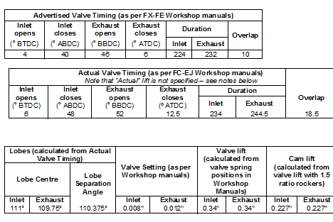 Note that the valve timing for all grey motor camshafts is the same. However, from FE engine number L418726 the grey motor camshaft was modified to give quieter valve train operation and to delay valve bounce to higher engine r.p.m.. This would indicate that the later camshafts have had the opening and closing ramps modified. This lets the valves open and close at the same angle, but slows down the valve as it approaches the seat. This stops the valve slamming into the seat, which can cause them to bounce off the seat. Another interesting change is that Workshop manuals from FC onwards start to report actual valve timing instead of advertised. Advertised timing shows when the valves just start to move typically when the lifter has moved 0.006 (the SAE standard distance). More useful numbers, which are often used to compare camshafts are the same measurements taken at a lifter movement of 0.050. This is probably what the actual numbers given in the FC and later workshop manuals are referring to (i.e. the FX-FE workshop manuals show the advertised durations, whilst the FC and later manuals show the durations at 0.050. However, it is not certain that 0.050 is the value GMH used
it could well be 0.040 for example (up until recently, camshaft manufacturers used a very wide variety of lifts to report this number). |
|
|
|
|
Logged
|
|
|
|
|
Harv
|
|
« Reply #94 on: January 20, 2014, 03:53:37 PM » |
0
|
The upshot of the above numbers can be summarized by showing how the valves are open as the camshaft spins clockwise. In the diagram below, TDC refers to Top Dead Centre (the piston right at the top of the cylinder bore), whilst BDC refers to Bottom Dead Centre (the piston right at the bottom of the cylinder bore). For our inlet valve, we get the diagram below (using the Advertised numbers) for a bog-stock grey motor camshaft. 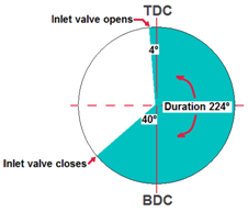 Starting in the upper left corner of the circle and moving around clockwise, our piston is finishing the exhaust stroke (pushing out exhaust gases). At 4º above the top of the stroke the inlet valve opens, using some of that exhaust gas flow to suck in the inlet charge. Our piston hits the top (TDC) and starts moving downwards, with the inlet valve open and inlet charge flowing into the cylinder. The piston reaches the bottom of its stroke (BDC) and starts moving up, compressing the charge. Our inlet charge has been flowing flat-out through the open inlet valve, and the inertia keeps bringing gas in even though the piston is beginning to compress. At 40º after BDC, the inlet valve closes and we continue compression against shut valves. Our inlet valve has been open for a total of 224º (this is referred to as 224º duration). Note that this is normal, and more than the 180º we would expect if the inlet valves only ever opened on the inlet stroke. |
|
|
|
|
Logged
|
|
|
|
|
Harv
|
|
« Reply #95 on: January 20, 2014, 03:54:23 PM » |
0
|
For our exhaust inlet valve, we get the diagram below (again using Advertised values) for our bog-stock grey motor. 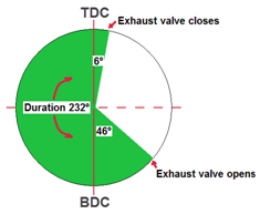 Starting in the bottom right corner of the circle and moving around clockwise, our piston is finishing the power stroke (moving downwards under the ignited fuel/air mix). At 46º before the bottom of the stroke the exhaust valve opens, using some of the cylinder pressure to start pushing out exhaust gas. Our piston hits the bottom (BDC) and starts moving upwards, with the exhaust valve open and flowing out exhaust gas from the cylinder. The piston reaches the top of its stroke (TDC) and starts moving down, beginning the inlet stroke. We leave the exhaust valve open for another 6º, using the flowing exhaust gas to help suck in the incoming air/fuel charge. At 6º after TDC the exhaust valve closes and we continue our intake stroke. Our exhaust valve has been open for a total of 232º duration. Again, this is normal, and more than the 180º we would expect if the exhaust valves only ever opened on the exhaust stroke. |
|
|
|
|
Logged
|
|
|
|
|
Harv
|
|
« Reply #96 on: January 20, 2014, 03:54:57 PM » |
0
|
Of note, there is a period when both the intake and exhaust valves are both open the inlet opens to let the fuel/air charge in, and the exhaust remains open to use its flow to help suck in the inlet charge. This period with both valves open is known as overlap. For our bog-stock grey motor camshaft, the Advertised overlap is 10º, as can be seen in the diagram below. 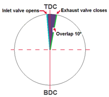 Big message here inlet and exhaust valves open earlier and close later than the inlet and exhaust strokes to help fill (or empty) the cylinder, and sometimes are both open at the same time. That early and late behavior is called cam timing, and needs looking at when we change things with a supercharger. |
|
|
|
|
Logged
|
|
|
|
|
Harv
|
|
« Reply #97 on: January 20, 2014, 03:55:31 PM » |
0
|
As an aside, to help put the above numbers into perspective a common way of describing aftermarket camshafts is in terms of two numbers (for example 30/70 or 40/80). The two numbers refer to the angle that the intake opens and closes (it assumes that the exhaust valves open at a similar angle). The bigger the numbers the more duration, and the lumpier the camshaft. For example, for a 30/70 cam: Intake opens at 30º BTDC (remember that the standard grey motor cam opens at 4º... the 30/70 opens the inlet much earlier), Intake closes at 70º ABDC (much later than the standard 40º), Exhaust opens at 70º BBDC (much earlier than the standard 46º), and Exhaust closes at 30º ATDC (much later than the standard 6º). The duration for this cam is 280º (30º+70º+180º) for both inlet and exhaust, which is longer than the standard camshafts 224º inlet duration and 232º exhaust duration. Overlap for this cam is 100º (30º+70º) which is much larger than the standard camshafts 10º. Note that the standard camshaft is not quite so equal in valve opening and closing (i.e. the exhaust and inlet valves do not open, nor close, at the same angle). This makes it hard to describe the standard grey motor cam in the same way as a 30/70. However, if we take some average numbers, the standard grey motor camshaft is roughly a 5/43. The last aspect of our standard camshaft is valve lift. The higher the valve lift, the more the valve will open. This gives increased flow of gas (kind of like turning on a bathroom tap more to fill the bath faster). In the diagram below, the red camshaft is a low-lift cam. The arrows show that the valve does not open much. The green camshaft is a high-lift cam. The red arrows show the red cam opens the valve much more, allowing for better gas flow. For our standard grey motor camshaft, the valve lift is 0.34. 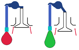 |
|
|
|
|
Logged
|
|
|
|
|
Harv
|
|
« Reply #98 on: January 20, 2014, 03:56:30 PM » |
0
|
Now that we understand the standard grey motor camshaft, we need to think how it will behave when a Norman supercharger is bolted on. Notwithstanding the discussion below, the overall message is that many supercharged motors run perfectly well with the stock (naturally aspirated) camshaft. Equally, the advice from several sources (for example Supercharged! Design, Testing and Installation of Supercharger Systems) indicates that if in doubt the stock camshaft should be used. This feels like sound advice given that the early Norman superchargers were designed to operate with the standard grey or red motor camshaft. However, the above is not to say that a change in camshaft (increased duration and higher valve lift) cannot bring about increased performance in a Norman supercharged grey motor. When we look at typical naturally aspirated hot grey motor cams, it is apparent that a major change is an increase in overlap, duration and lift. For example, for the range of Camtech Cams (and one of the Waggot cams): 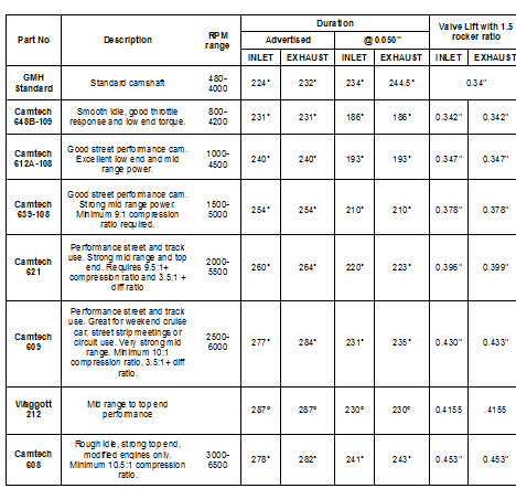 As we move down the table (increasingly hotter cams), the inlet and exhaust duration increases, as does valve lift and overlap. When considering a change to the standard grey motor camshaft to accommodate a Norman supercharger, there are two key issues that we wish to address. The first issue is probably the more important of the two. Adding a supercharger to the engine will greatly increase the flow of gases (intake and exhaust) through the engine. Whilst the intake side flows better because of the boost pressure, the exhaust side still relies on cylinder pressure to blow the gases out. The simple way to think of this is that there is no point adding a supercharger and jamming more air in, if we cannot get that air to flow back out again. This means that we want a camshaft that: a) lifts the exhaust valve higher for more gas flow (i.e. fills the bathtub faster by opening the tap more), and/or b) holds the exhaust open longer to allow the additional exhaust gas more time to flow (i.e. a longer exhaust duration). We can increase exhaust duration by opening the valve earlier (as per the pale green area in the diagram below), or by closing it later (as per the orange area in the diagram below). Whilst both changes will work, closing the valve later can cause some issues, particularly at low engine rpm. 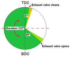 |
|
|
|
|
Logged
|
|
|
|
|
Harv
|
|
« Reply #99 on: January 20, 2014, 03:57:12 PM » |
0
|
This brings us to the second issue, which is related to the cam overlap. Naturally aspirated engines have camshafts with large amounts of overlap, which uses the exhaust flow to help suck in inlet air/fuel, especially at higher rpm. However, our supercharged engine has a pressurized inlet manifold, so needs this inlet charge encouragement less. In a supercharged engine with high overlap, what tends to happen is that the pressurized inlet charge blows into the cylinder and straight out the open exhaust valve. This will give poor economy and poor emissions performance, and can lead to a loss of performance at low engine speed where boost is low. In the overlap diagram below we can see that by closing the exhaust valve later (trying to increase exhaust duration for our supercharged grey motor), the orange area would increase overlap. 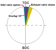 More importantly, increasing overlap will also reduce the boost pressure. As a guide (From Supercharge!), the boost pressure will fall by about 5% of absolute pressure for each 10º by which valve overlap is increased. The standard (advertised) overlap is 10º, giving the following boost reductions: 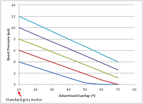 For example, a grey motor running 10psi boost with the standard camshaft will drop to 5psi if the overlap is increased to 50º. Whilst the overlap may be of help at high RPM, it will lead to a low boost, sluggish vehicle at low RPM. For this reason, we generally want a camshaft for our Norman supercharged grey motor with as little overlap as possible. This means that to get better exhaust flow we are looking for a camshaft with higher exhaust valve lift, or that opens the exhaust valve earlier (not closes it later). In short if we want good all round driveability (most Norman supercharger installations), the standard camshaft is a good choice. The later camshaft (mid FE Holden onwards) is better than the earlier grey motor camshaft, as it will delay valve bounce without affecting timing. If we do not mind sacrificing some low-end drivability and emissions, then we are looking for a camshaft with increased lift, increased exhaust duration (through opening the exhaust valve earlier) and preferably low overlap. |
|
|
|
|
Logged
|
|
|
|
|


