|
Harv
|
 |
« Reply #100 on: January 20, 2014, 03:58:03 PM » |
0
|
There are a number of Australian camshaft grinders who can regrind the original grey motor camshaft to suit high performance applications. These include Wade, Camtech, Clive Cams, Tighe and Waggot. Note however that most camshaft grinders do not have dedicated supercharger grinds for the Holden grey motor, and instead rely on the high performance naturally aspirated grinds. This is different to say small block Chevrolet engines, where supercharging is more common and camshaft grinders are able to supply dedicated supercharger grinds. As an example, for a mildly blown grey (5-10psi of boost and primarily street use) Camtech recommends the Part Number 609 camshaft shown in the table above. This will increase advertised exhaust duration from 224º to 284º, though notably will also increase advertised overlap from 10º to 64º. This is a substantive degree of overlap, and would see a 10psi blown grey motor lose almost half the boost pressure
perhaps not an issue for all-out sustained high-RPM work, but of serious concern with a street engine. As a comparison, the table below shows the range of supercharger camshafts available from Weiand (via Lunati) for small block Chevrolets. Note that the durations remain long for good exhaust flow, being increased from a typical factory 270º to 290º (especially in the 01006 and 01007 performance cams). More notably, the advertised overlap has been reduced from a typical factory SBC value of 35º to nil
a far cry from the 64º grey motor camshaft recommended by Camtech above. The exception is the 01007 camshaft with 25º of overlap (still a far cry from 64º), though Lunati note that this is only suitable for high boost engines probably due to the boost loss at low RPM. 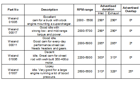 In short, supercharged camshafts are readily available for motors like small block Chevrolets, but are not so common (if available at all) for the Holden grey motor. To get your hands on a blower cam for a supercharged grey motor will require custom cam grinding
expensive to say the least. The upshot of the above is again that for most Norman supercharged grey motors the standard stock camshaft should be used. For sustained high-RPM use a normal grey motor hot cam (performance grind) may be suitable though a) will take some trial and error to balance the resultant boost loss against high RPM power gains. b) will drop boost at low RPM. c) Will blow more unburnt fuel out the exhaust at low RPM. Cheers, Harv (deputy apprentice Norman supercharger bumpstick fiddler). |
|
|
|
|
 Logged
|
|
|
|
FC427
nsw-club
Guru

 Offline Offline
Model: FC
Posts: 2457
I love YaBB 1G - SP1!

|
|
« Reply #101 on: January 21, 2014, 09:41:34 AM » |
0
|
|
|
|
|
|
Logged
|
As I lay rubber down the street I pray for traction I can keep, but if I spin and begin to slide please dear god protect my ride
|
|
|
|
Harv
|
|
« Reply #102 on: January 21, 2014, 12:31:25 PM » |
0
|
Just for those that say the old Red 6 doesn't sing A blown methanol Injected 6 ........FC427.......... 9,000rpm? Must have had the switch at the back of the tacho set to "8" instead of "6"  Only kidding - gotta have a lot of respect for anyone who can take a fifty year old motor and squeeze as much grunt out of it as some of the red motor crowd do. That kind of knowledge comes at the expense of many, many loud bangs and subsequent rebuilds. Cheers, Harv |
|
|
|
|
Logged
|
|
|
|
|
Harv
|
|
« Reply #103 on: January 26, 2014, 09:57:10 AM » |
0
|
Our last post looked at the intake timing needed to get our Norman blown grey motor to breathe. This post will look at the other side of breathing our SU carburetor, and what changes we may need to make to the standard SU. One issue commonly referred to when carbureted superchargers are discussed is the need for a blower carb, or a boost referenced carb. Boost referencing a carburetor is a modification (often done to Holley carburetors) to allow the power valve to take signal from between the supercharger and engine. The power valve is used (on some carburetors like Holleys and B-model Strombergs) to provide additional fuel under heavy load. On a normally aspirated engine (for example a standard grey motor with single BXOV-1 Stromberg carburetor) the power valve takes it signal from the inlet manifold. The manifold vacuum at idle holds the power valve closed, preventing the mixture getting too rich see the image below left. Under heavy load, the manifold vacuum decreases, allowing the power valve to open and richen up the mixture see the image below right. 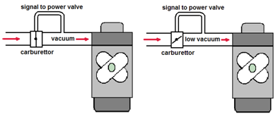 On a suck-through supercharger system (like the Norman superchargers) a normal power valve will see vacuum under idle, as per the image below. This keeps the power valve shut as required. 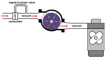 However, under load the supercharger can draw hard enough that vacuum continues to exist between the supercharger and carburetor. If the power valve is taking its signal from between the supercharger and carburetor (as per the image below), then the power valve will never open, leading to lean-out under load.  |
|
|
|
|
Logged
|
|
|
|
|
Harv
|
|
« Reply #104 on: January 26, 2014, 09:57:45 AM » |
0
|
Many Holley carburetors for suck-through supercharging are thus boost referenced by drilling and tapping the vacuum signal between the supercharger and engine as per the image below (an alternative for Holleys is just to pull out the power valve altogether, and to run overly rich main jets). 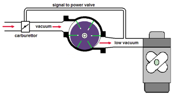 The SU carburetor however does not utilize a power valve for full-throttle enrichment, and instead relies on the needle profile. SU carburetors in suck-through configuration are thus not boost-referenced (though as noted above may need to have an additional weakening device fitted to allow for overly rich part-throttle mixtures). As an aside, SU carburettors can also be used in blow-through installations (such as was done from the factory for the MG Metro which used a Garrett T3 turbo blowing through a SU HIF44). In a blow-through supercharger installation, a number of other modifications are required to an SU carburettor, primarily sealing the carburettor (or mounting the entire carburettor in a pressurised box) to prevent fuel and air being blown out. This is not required for the Norman supercharger due to the suck-through installation. |
|
|
|
|
Logged
|
|
|
|
|
Harv
|
|
« Reply #105 on: January 26, 2014, 09:58:30 AM » |
0
|
When operating with a naturally aspirated engine, the carburetor can become the limiting factor on horsepower. The Holden grey motor is a good example of this, with the original single Stromberg carburetor being fairly asthmatic. A common way of increasing horsepower is to increase the number of carburetors (twins or triples), or to debottleneck the existing carburetor. There are a number of tricks that can be applied to carburetors to make them flow more air. For our Norman supercharged grey motor, we are likely to be running SU carburetors. The standard SU carburetor can be modified to flow around one third more air than standard. As an example, the following modifications can be made to a HS4 carburettor (I have taken this information from Tuning BLs A-Series Engine, by David Vizard): 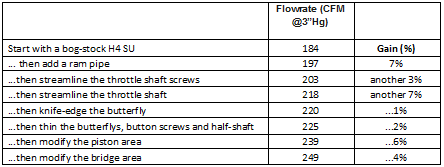 Bear in mind that our supercharged grey motor, making around 110BHP will want around 50% additional air flow over the standard GMH engine. As we noted in earlier posts above, two 1½ SUs or a single 2 SU are suitable for supercharged grey motors, whilst for those not chasing grunt a single 1¾ or two 1¼ SUs may suffice. If we were running short on carburetor capacity (CFM) for our Norman sueprcharged grey motor, it is probably just as easy to increase the size of the SUs used (or the number of SUs) than to undertake the kind of modifications above. The capacity of various SU carburettors is given below: 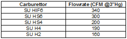 The upshot of this is that as a general guidance, there is little need to increase the air flow capacity of SU carburetors for Norman superchargers choose the right number and size instead. |
|
|
|
|
Logged
|
|
|
|
|
Harv
|
|
« Reply #106 on: January 26, 2014, 09:59:10 AM » |
0
|
However, when engine bay space prevents additional carburettors (or budget means you need to use the SUs that you already have), there are some sensible choices to be made. The last two modifications in the table above (modifying the piston and bridge areas) are not for the faint hearted, and are not reversible. Unless you are looking for every last ounce of horsepower from an existing carb, then they are probably not worth doing. Thinning the throttle shaft is another area with a decent flow gain, though again not for the faint hearted. One modification not noted above is the removal of the SU carburettor over-run limiting valves (often called a poppet valve see the red arrow in the images below). 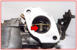 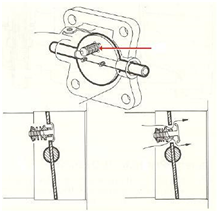 This modification was present on the SUs on my large Norman, which was allegedly fed one of Mike Normans race vehicles. The over-run limiting valve is a precisely set spring-loaded plate valve is located in the throttle disc. When the throttle is snapped shut, very high vacuum can develop in the inlet manifold. If the vacuum is greater than about 22"Hg, the mixture becomes too weak to ignite easily, causing misfire. This can result in unburnt fuel passing into the exhaust system where it can detonate (backfire). The over-run valve opens under high manifold vacuum conditions (i.e. when the throttle is snapped shut), reducing the vacuum and supplying a quantity of correct fuel/air mixture through the throttle disc. The correct combustion achieved reduces both backfiring and emissions. The over-run limiting valve can be readily removed, and the resultant throttle disc hole soldered up. This is a moderately simple change, and is probably good for around 5% or so extra flow. Whilst this change is reversible, it will entail replacing the throttle plates. |
|
|
|
|
Logged
|
|
|
|
|
Harv
|
|
« Reply #107 on: January 26, 2014, 10:00:46 AM » |
0
|
The change above that does deliver moderate increases in air flow, is simple and easily reversible is adding a ram tube to the inlet of the carb. A ram tube and associated filter (either sock-type or an enclosed K&N type filter) is a cheap investment, looks period correct and delivers a little extra flow, all of which would appear worthwhile. Note however that not all ram tubes are created equally. The diagram below (again from Tuning BLs A-Series Engine, by David Vizard) shows different type ram tubes, and the % flow increase seen over a standard SU carburetor. 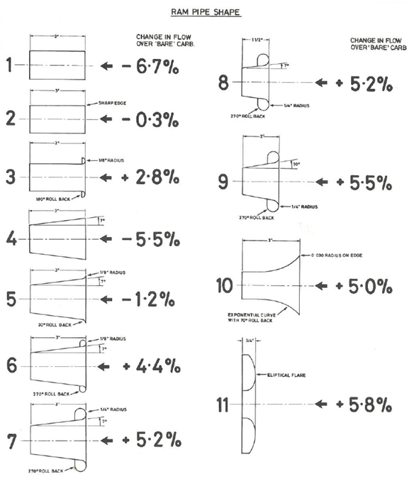 The message here is that care needs to be taken in selecting the right shape ram tube, and that a smooth, radiused edge with good rollback is most likely to be successful. Pictured to below to the left are the ram tubes offered by SU Midel, which have a large radius and high rollback (these are like types 7, 8 and 9 above a good choice). 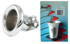 Pictured to the above right are the ram tubes offered by Redline Performance Products which are similar to type 10 above again a good choice. Notice that ram tubes of the types 1 and 4 in the image above show a substantial flow loss over the standard SU carburetor choosing ram tubes of this type could well lead to the Norman supercharger being strangled for air, particularly if the size (or number) of SUs was marginal in the first place. The overall message here is that for our Norman supercharged grey motor we will use a suck-through configuration, utilize big enough SU carburetors (or enough small ones) to suit the air flow required, probably leave the SU internals standard, and if fitting a ram tube to the inlet will need to take care of what shape it is in order to prevent a flow restriction. Cheers, Harv (deputy apprentice Norman supercharger fiddler). |
|
|
|
|
Logged
|
|
|
|
|
Harv
|
|
« Reply #108 on: March 11, 2014, 08:29:11 AM » |
0
|
As discussed above, Norman superchargers require a relief valve in order to operate safely. Whilst this is somewhat fiddly, the results of not using one can be catastrophic. Ive stolen the photo to the right from Pete, which shows what a blower backfire can do to an aluminium manifold. This setup was running 6psi on a positive displacement suck-through setup on a red motor
. kinda similar to a Norman. As well as bursting the welds, the blower bang also managed to blow the Teflon off the seals: 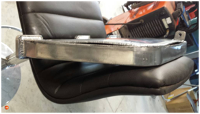 Blower bangs can be very, very nasty if no relief valve is fitted. Ever wonder why many GMC supercharged motors have blower restraints (as well as a burst panel)? To stop the blower rocketing off into the stands should a blower bang. Some guidance to relief valves is contained in Supercharge!: Mount the relief valve as close to the supercharger as possible. Consider a relief valve at both ends of the manifold. Relief valves should be of considerable area. For a 3-litre motor they should be at least 4 inch2 (for example a square hole 2x2, or a round hole of 2¼ diameter). Relief valves should be set to 50% more than the manifold pressure maximum (for example if we wish to deliver 10psi boost, the relief valve should be set at 15psi). |
|
|
|
|
Logged
|
|
|
|
|
Harv
|
|
« Reply #109 on: March 11, 2014, 08:29:54 AM » |
0
|
Very, very rough calculations show that Eldreds sizing of 4 inch2 is appropriate for the red motor type Normans (200ci/rev) operating around 4500rpm. The smaller Normans (80ci/rev) would still need around 2 inch2, though are safer at 4 inch2. The relief valves favoured by Eldred are a plate type, consisting of a moving aluminium disc on an edge seal. The disc covers a round hole in the inlet manifold. The disc is located by three guide studs arranged around the circumference of the disk. The studs also holds a fixed triangular retainer. A set of springs (often reused valve springs) go between the triangular retainer and the aluminium disc. The drawing and photos to the right show this type of relief valve. The relief valve pop pressure is set by tightening the stud nuts down. 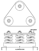 The dimensions shown in the image below have been taken from a working Norman supercharger (my water cooled Norman). The image (from left to right) shows the aluminium disc, retainer and a rubber washer that had been used under the disk. The washer may be needed if the aluminium edge seal is not quite true, either from poor original machining or from being smacked around over time when the valve pops. The valve had been fitted over a 1.79 diameter hole in the manifold, giving a relief valve size of 2.5inch2. As seen above, this is probably the smallest size valve suitable for a grey motor type Norman, and undersized for the larger red motor sizes. Three ¼x3 long bolts were utilized to mount the assembly. The valve had been fitted with a spring with dimensions as shown in the bottom right of the image. The spring had a stiffness of 124lb/inch, and a potential to compress up to 0.9 before reaching coil bind (note that this is stiffer than a typical used grey motor valve spring, which have tension of around 85lb/inch and a potential to compress up to ~1 before reaching coil bind). This gives the ability to adjust the valve to a manifold relief pressure from zero to 135psi (fitting a used grey motor spring would give a pressure range of zero to 100psi). Using Eldreds 50% guidance above, this means that we could run the supercharger at up to 90psi with the spring fitted, or up to 67psi with the grey motor valve springs used... not that we would ever be running a Norman at those pressures. 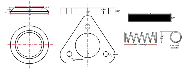 |
|
|
|
|
Logged
|
|
|
|
|
Harv
|
|
« Reply #110 on: March 11, 2014, 08:30:49 AM » |
0
|
|
|
|
|
|
Logged
|
|
|
|
|
Harv
|
|
« Reply #111 on: March 11, 2014, 08:33:08 AM » |
0
|
Realistically, the Weiand, Blower Shop and AussieSpeed valves do not have sufficient size to act as back fire valves for the Norman supercharger unless a separate (and much larger) burst panel is employed.
Supercharger relief valves should be pressure tested before the manifold is fitted to the vehicle. To do this, all openings are blanked off with flat steel plate, using rubber sheet gaskets. A compressed air hose and gauge is fitted and the pressure slowly increased until the relief valve pops, taking care not to overpressure the manifold should the valve stick. The adjusting nuts are then tightened or loosened, and the process repeated until the desired set pressure is achieved. WARNING: Pneumatic testing a manifold like this is dangerous. If the manifold fails before the valve open, it can fragment and throw pieces of metal a long way, and very fast. The pop pressure should be approached very, very slowly and not exceeded if the valve does not lift. Faceshield definietley recommended for this one. If you have the ability to use water pressure instead of air, this is a much safer approach (water does not compress and contain as much energy as air).
Cheers,
Harv (deputy apprentice Norman supercharger fiddler).
|
|
|
|
|
Logged
|
|
|
|
|
Harv
|
|
« Reply #112 on: March 14, 2014, 06:53:27 PM » |
0
|
A quick update on some of the measuring that has been going on. Attached below is an update of the rotor drawing for the various Norman superchargers. The aim by the end is to end up with a decent set of drawings of the entire setup (rotors, casings, manifolds and drives). This should be useful for the next guy trying to fabricate manifolds, or seeing whether a given Norman will fit under the bonnet. 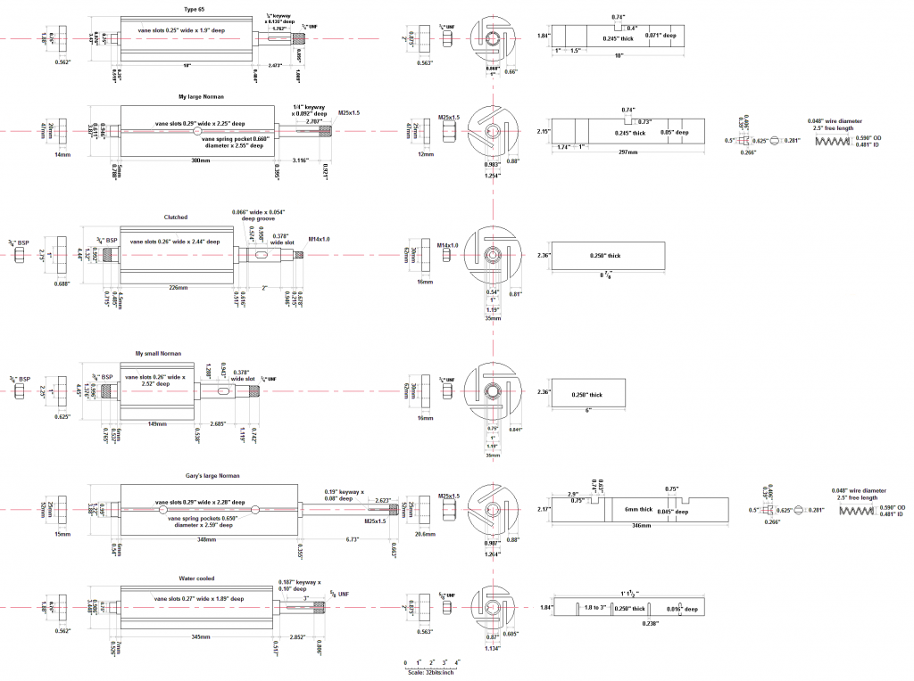 Apologies again for the thread jumping around a bit - that's the price you pay for doing this as a thread rather than a Guide. Cheers, Harv (deputy apprentice Norman supercharger fiddler). |
|
|
|
|
Logged
|
|
|
|
|
Harv
|
|
« Reply #113 on: March 14, 2014, 07:40:22 PM » |
0
|
For this post, I will take a look at the registration hurdles we are likely to face in installing a Norman sueprcahrger to our early Holden. In an ideal world, supercharging our Holden grey motor would be as simple as bolt up and go. The bolt up part is tricky enough in itself. However, installing a supercharger is a modification which requires engineering certification. Supercharging has the capacity to substantially increase a vehicles power and performance and is generally considered on the same basis as a performance engine conversion (like installing a V8). In the information below, I will summarise the requirements from the National Code of Practice (NCOP) Supercharger and Turbocharger Installation Code LA3. Before anyone asks, I know full well that some engineers will pass a vehicle with substantially less than the below, and that some registration authority inspection stations will issue a roadworthy regardless of what is under the bonnet (but my cuzzy has a blowa on his fooly sick Monaro mate, 1000hp, no engineers mate) I am only aiming to show what the guidelines are. Our starting point is to determine exactly when certification for a supercharger is required. The table below gives some guidance. Essentially, if we are aiming for more than a 20% power increase (and we should be!), then certification will be required. Assuming that we are Norman supercharging our grey motor, then Code LA3 applies. 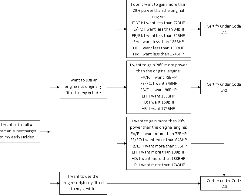 |
|
|
|
|
Logged
|
|
|
|
|
Harv
|
|
« Reply #114 on: March 14, 2014, 07:40:57 PM » |
0
|
Code LA3 specifies a number of requirements, listed below. Because FB/EK Holdens are pre-ADR, a number of mandatory safety upgrades are required. These are:
Seatbelts must be installed for all seating positions (all outboard seating positions require retractor type lap/sash seatbelts and inboard seating positions either lap/sash or lap belts),
Split or dual braking system. As the early Holden brake systems are single, this requires a new master cylinder and appropriate piping.
Windscreen washers must be fitted. This could be a period type Trico set up, or an el-cheapo plastic bottle and pump from SuperCheap Auto.
Two speed windscreen wipers with a fast speed of at least 45 cycles per minute and a slow speed of at least 20 cycles per minute must be fitted. Note that the original FB/EK single speed wipers are acceptable provided yours can be shown to have a cycle speed of 45 cycles per minute or more.
A windscreen demister must be fitted. This could be a period Warmaride heater, an electric aftermarket heater or as simple as a 12V hair dryer plumbed into pool cleaner hose.
A flat or convex external rear vision mirror complying with the latest version of ADR14 must be fitted to the drivers side of the vehicle.
Flashing direction indicator lights must be fitted at the front and rear of the vehicle (not a problem from EK onwards, though an option for earlier Holdens).
The engineer signatory may specify a higher tyre speed rating than the original specifications and the fitting of an additional tyre placard indicating the minimum tyre requirements. The load rating of tyres must not be reduced from that specified by the vehicle manufacturer.
A collapsible steering column must be fitted.
|
|
|
|
|
Logged
|
|
|
|
|
Harv
|
|
« Reply #115 on: March 14, 2014, 07:43:01 PM » |
0
|
Additionally, Supercharger drive belts and pulleys must be shielded to prevent injury from accidental contact with rotating components. With respect to emissions, as our early Holden was manufactured prior to 1986, no emissions tests (as called up through ADR 37/00) apply. Similarly, because our early Holden was not certified to ADR83/00 (2005), a noise test is not required. Whilst the original Norman supercharger installations on early Holdens were contained under the bonnet, this may not be possible for all configurations. Any supercharger and induction system components sticking up above the original bonnet line must be covered with a bonnet scoop/bulge meeting the following: a) the top surface of the scoop/bulge must not be more rigid than the original bonnet. b) the scoop/bulge must be low rise. To check this, a 165mm diameter circle is placed on the bonnet in front of the scoop/bulge and rolled rearwards until it touches the scoop/bulge. The scoop/bulge must be low enough that no part of the scoop/bulge touches the circle above its centerline. 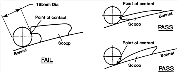 c) Whilst there is no maximum height specified for a scoop/bulge, it must not restrict the field of view of the driver under normal operating conditions. The drivers field of view requirements are determined by sitting in the drivers seat with the seat pushed right back. It must be possible to see either the surface of the road eleven meters in front of the drivers eye (red line in the diagram) or the front edge of the original body when looking across the top of the bonnet scoop (blue line in the diagram). 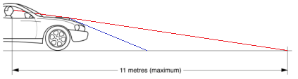 There are some fancy ways of working out how tall the driver is, but a simple way is to take the eye position as a point 730mm above and 270mm forward of the junction of the seat cushion and squab. For our FB/EK Holden, this means we can (roughly!) fit a 6 tall bonnet scoop as per the photos below. 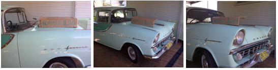 d) The edges at the front of a scoop/bulge likely to contact a pedestrian in a collision must be well rounded with a minimum of 10mm radius. All edges and corners must have a radius of not less than 5mm. e) The scoop/bulge must not have reflective surfaces that will cause glare. f) Plastic or fiberglass is acceptable, providing that the hole in the bonnet does not substantially reduce the strength or impact resistance of the bonnet and no rigid component (such as an air cleaner or carburetor) protrudes beyond the original bonnet profile. This kind of defeats the purpose if we are installing the scoop to cover a Norman supercharger installation. In reality, it means either the scoop is made of mild steel of the same thickness as the original bonnet, or everything is tucked under the bonnet. g) If any bonnet reinforcing braces are cut or modified, the bonnet must not be weakened and have no sharp edges. Cheers, Harv (deputy apprentice Norman supercharger fiddler). |
|
|
|
|
Logged
|
|
|
|
|
Harv
|
|
« Reply #116 on: March 20, 2014, 10:55:32 AM » |
0
|
For this post, we will take a look at rotor clearance and end-thrust. The rotor on a Norman supercharger is held in place by bearings at either end. The bearings are held in place to the end plates with circlips, preventing the bearing from moving axially. The means that when the bearings and end plates are installed, the casing, end plate and bearing are locked in position and cannot move relative to each other. In the overview image below, we can see: a) The rotor (grey) lying in the casing (yellow), b) The drive-end end plate (dark green) bolted to the right-hand end of the casing, with its bearing (dark blue) held in place by a circlip (pale green). Trapped between the end plate and bearing is the drive-end seal (purple). c) The non-drive end end plate (brown) bolted to the left-hand end of the casing, with its bearing (orange) held in place by a circlip (pale green). 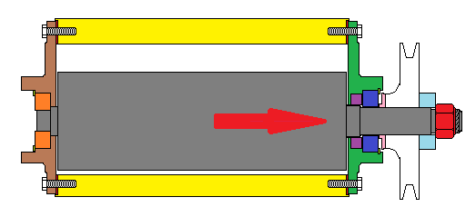 |
|
|
|
|
Logged
|
|
|
|
|
Harv
|
|
« Reply #117 on: March 20, 2014, 10:56:16 AM » |
0
|
The non-drive end bearing is often a two-piece bearing (like the Type 65s bearing), where the inner and outer races are able to be pulled apart by hand. Whilst this sounds strange, the inner race has a wire cage that retains the bearing balls. The two-piece design means that the non-drive end bearing cannot take any thrust load at all if the rotor shaft tries to move axially, the bearing simply slips out the inner race. This is useful in the Norman superchargers, as it allows the rotor steel to grow longer as it gets hot, expanding out through the rear bearing. If we assume that the rotor starts at ambient temperature (25ºC) and gets as hot as 75ºC, the 50ºC temperature change is likely to change the rotor length by around 0.06%. This means a Type 65 rotor will grow some 0.006. Whilst this does not sound like much, bear in mind that typical cold end-clearance between the rotor and casing is 0.010-0.015 at the drive end and 0.025 at the non-drive end. As the rotor expands, it takes up quite a bit of the extra clearance at the non-drive end. The cold end-clearance between the rotor and casing at the non-drive end is determined by the thickness of the gaskets (shown in red in the attached diagram) between the end plates and casing (both drive end and non-drive end). The thicker the gaskets, the more clearance at the non-drive end. The drive-end bearing is a one-piece bearing. Pressing up against the bearing is a thrust washer (shown in pink in the diagram above). The thrust washer is stepped so that it bears on the bearing inner race only. The thrust washer is keyed to the rotor shaft, though free to move along it. Pressing up against the thrust bearing is the drive pulley (shown in white), again keyed to the rotor shaft though free to move along it. Pressing up against the pulley is a pulley washer (shown in pale blue), followed by the shaft nut (shown in red). This is where things get interesting. When the drive-end assembly is put together and the shaft nut is tightened up, it begins to draw the rotor through the drive-end plate, bearing, pulley and washers (in the direction of the red arrow in the diagram). This reduces the cold end-clearance between the rotor and casing at the drive end. Thus for the drive-end, the cold end-clearance between the rotor and casing is determined by how far the drive nut is tightened. When assembling the supercharger, care must be taken not to flog the hell out of the shaft nut, as this will change the clearance. The shaft nut should only be adjusted with the end-plate off the casing so that the cold end-clearance between the rotor and casing at the drive end can be checked with feeler gauges. If the shaft nut is adjusted with the end casing on, it is not possible to determine what the resultant clearance will be. This also means that the nut must not move during operation (say by vibration). It is thus important that the shaft nut be a lock-nut in good condition not one that has been assembled/disassembled until the nylon is worn. An alternative to using nylock lock nuts is to use two jam nuts. This is prevalent in the later (Mike) Norman superchargers, where castellated jam nuts are used see the image below, where one of the two castellated nuts has been removed whilst the other remains on the shaft. 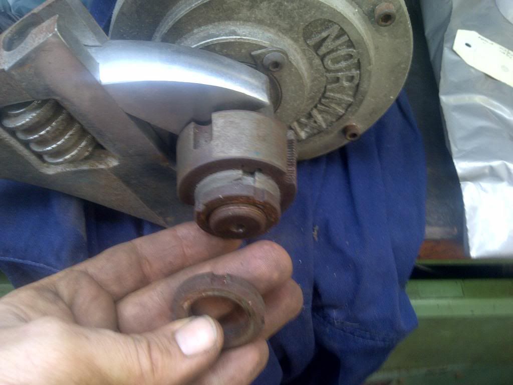 |
|
|
|
|
Logged
|
|
|
|
|
Harv
|
|
« Reply #118 on: March 20, 2014, 10:56:51 AM » |
0
|
The process of having clearances set by the lock-nut occurs when the pulley washer is sized as per the image labelled 1 in the diagram below. 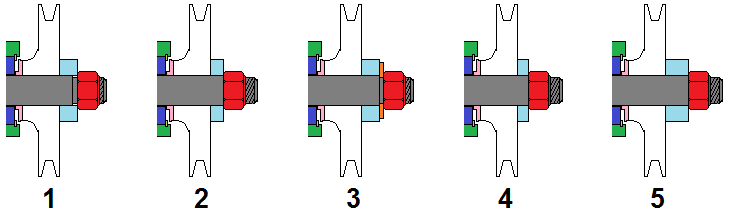 One way to limit the risk of shaft nut movement is to blueprint the pulley washer. This is done by allowing the shaft nut to bottom-out on its threads as per the image labeled 2. The shaft nut can then be torqued up tight, lowering the chance of movement. This then means that the cold end-clearance between the rotor and casing at the drive end is independent of how far the drive nut is tightened, and instead is determined by the thickness of the pulley washer. The pulley washer thickness is then chosen so that the cold end-clearance between the rotor and casing at the drive end is correct (around 0.010). A thicker pulley washer will decrease the end-clearance, as per the image labeled 5. Note that if adding additional washers/shims to make a thicker pulley washer, care needs to be taken that the additional washers/shims do not bear against the shaft step, as shown by the orange shims in the image labeled 3. Shims/washers that bear on this step do not decrease the end-clearance... they just drive the shaft nut along the shaft. A thinner pulley washer will increase the end-clearance, as per the image labeled 4. Overall, the process for setting the end clearances then becomes: a) Install the bearing into the drive end plate. b) Install the drive end plate/bearing assembly onto the rotor. c) Install the thrust washer, drive pulley and pulley washer onto the rotor. d) Tighten the shaft nut until it bottoms out. e) Check the cold end-clearance between the rotor and casing at the drive end with a pair of feeler gauges, aiming for 0.010. If the clearance greater than 0.010, install a thinner pulley washer (or skim down the existing one). If the clearance is less than 0.010, install a thicker pulley washer or shim washer. f) Install the non-drive end bearing inner race onto the rotor. g) Install the clearanced rotor and end-plate assembly to the casing together with an appropriate gasket. h) Install the outer bearing into the non-drive end plate. i) Fit plastigauge to the non-drive end of the rotor. j) Install the non-drive end plate/bearing assembly onto the rotor/casing casing together with an appropriate gasket. k) Remove the non-drive end plate/bearing assembly from the rotor/casing casing. Check the end-clearance by reading the plastigauge, aiming for 0.025. If the clearance is less than 0.025, replace the end-plate gaskets with thicker ones. If the clearance is more than 0.025, replace the end-plate gaskets with thinner ones. With respect to bearing thrust, there is not a huge amount of thrust loading in a Norman supercharger. The main culprit for thrust loading is (often minute) amounts of misalignment between the crankshaft and supercharger pulleys. The Norman supercharger (and its Judson cousin) relies on an interference fit on the rotor shaft to hold the rotor in place there is no effective thrust bearing. If the rotor tries to move in the direction of the red arrow in the diagram, it can slip through the bearings. This reduces the end-clearance between the rotor and casing at the drive end and can cause end-plate gouging. This would be the case if the crankshaft pulley is too far forward (in front of the supercharger pulley). If the rotor tries to move opposite the direction of the red arrow in the diagram, the shaft nut, pulley washer, pulley and thrust washer will bear up against the drive end bearing inner race, preventing rotor movement. This would be the case if the crankshaft pulley is too far backwards (behind the supercharger pulley). Whilst not catastrophic, it is not great practice to load up a ball bearing in this fashion. Given the above limitations in thrust control, it is important that supercharger pulleys are adequately aligned. This is a particular issue when vee-belts are used, and less of an issue where non-shouldered gilmer belts are employed. Cheers, Harv (deputy apprentice Norman supercharger fiddler). |
|
|
|
|
Logged
|
|
|
|
|
FCRB26
|
|
« Reply #119 on: March 20, 2014, 11:39:30 AM » |
0
|
Sorry to jump on your thread harv
But i would really like to hear if im heading in the right direction.
I have made this mod to a new manifold and am running 6 springs to hold positive pressure on the plate to seal it.
I am going to machine an o ring seal in the plate and lace an o ring around the cutout.
So if it bangs it pops the whole plate down.
You have me thinking there is a ton of gas there and a massive build up of energy to get rid of.
Tapa talk is playing up ill try to add pics
|
|
|
|
« Last Edit: March 20, 2014, 11:52:29 AM by FCRB26 »
|
Logged
|
|
|
|
|


