|
Harv
|
 |
« Reply #280 on: January 03, 2015, 07:52:02 PM » |
0
|
This is a fascinating thread Harv. Thanks for taking the time to share your knowledge. Thanks Alex. I'm learning a heap along the way, including some stuff I'd always assumed (who would have thought gilmer belts could be so damn complex). I've also gotten to meet some very skilled individuals. Will that carby clear an FC bonnet? I hope not  . Definitely doesn't fit under an FB bonnet. Cheers, Harv |
|
|
|
|
 Logged
|
|
|
|
|
Harv
|
|
« Reply #281 on: April 15, 2015, 06:41:21 PM » |
0
|
Ladies and gents, This post contains some odds and ends that I have learnt over the last few weeks. Apologies if it seems a bit random
thats one of the downsides of me writing this as an ongoing forum thread rather than a completed Guide. A while back I took a good look at the rotor vane material. The vanes used in early (Eldreds) Norman superchargers are made from canvas Bakelite. This is made by applying heat and pressure to layers of cotton fabric impregnated with Bakelite (phenolic) resin to make a laminate, and can be identified by the brown colour. The later Norman superchargers (Mikes) vanes were changed to a more modern epoxy resin based binder over a fine fabric matrix, supplied by a firm in Sydney. The cream coloured material was much stronger and wear resistant than Eldreds Bakelite vanes. Mike could remember that it was labelled as something similar to F4 or F5, though we were not certain of the exact material. I had suspected that the material was either National Electrical Manufacturers Association (NEMA) FR-4 or FR-5 fire retardant glass-cloth reinforced epoxy laminate, but was not certain. FR-4 is a form of fibreglass. I put the search for Mikes material on the back-burner, but recently revived the issue when I needed to buy some replacement vanes. On working through the issue, it is unlikely that FR-4 or FR-5 was the material used by Mike. The main reason behind this is the hardness of the FR-4 material. The diagram below shows a number of hardness measuring scales on the left: HB (Brinnell hardness), HV (Vickers Harness), HRA (Rockwell A hardness), HRB (Rockwell B hardness), HRC (Rockwell C hardness), Scleroscope, HK (Knoop harndess) and Mohs Scale. These are various tests used to measure hardness, whose scales partially overlap. On the right are some materials, arranged against the scales in order or harness diamond at the top as very hard, and lead at the bottom as very soft. 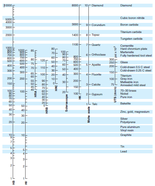 We can see that in the middle are cast iron and cold drawn steel, which were used for Eldred and Mikes respective casing liners. Note that Bakelite is lower on the scale than either of cast iron or cold drawn steel. This means that Eldreds Bakelite vanes are softer than the casing liners, and will wear out. This is a good thing
if the vanes wear out they can be easily replaced, but a worn-out bore is fatal. When the Bakelite starts to wear out, it exposes the cotton fibres in the resin. These are softer than the iron, and again do no damage to the liner. FR-4 has a very similar hardness to Bakelite - about 110HRM when measured on the Rockwell M hardness scale. At first glance, it thus appears that FR-4 is softer than iron or steel, and hence an acceptable choice for the vanes. However, the Rockwell hardness test is really measuring the hardness of the FR-4 resin binder that is on the surface of the vane. As an FR-4 vane wears down, the soft resin binder is worn away, and the glass material becomes exposed. Glass is very much harder than steel, as we can see from the diagram above. The upshot is that for FR-4 vanes, the nice soft resin binder wears out, then the hard glass reinforcement would wear the hell out of the casing. This is why FR-4 is not a suitable material for supercharger vanes. |
|
|
|
|
Logged
|
|
|
|
|
Harv
|
|
« Reply #282 on: April 15, 2015, 06:45:03 PM » |
0
|
We can see that in the middle are cast iron and cold drawn steel, which were used for Eldred and Mikes respective casing liners. Note that Bakelite is lower on the scale than either of cast iron or cold drawn steel. This means that Eldreds Bakelite vanes are softer than the casing liners, and will wear out. This is a good thing
if the vanes wear out they can be easily replaced, but a worn-out bore is fatal. When the Bakelite starts to wear out, it exposes the cotton fibres in the resin. These are softer than the iron, and again do no damage to the liner. FR-4 has a very similar hardness to Bakelite - about 110HRM when measured on the Rockwell M hardness scale. At first glance, it thus appears that FR-4 is softer than iron or steel, and hence an acceptable choice for the vanes. However, the Rockwell hardness test is really measuring the hardness of the FR-4 resin binder that is on the surface of the vane. As an FR-4 vane wears down, the soft resin binder is worn away, and the glass material becomes exposed. Glass is very much harder than steel, as we can see from the diagram above. The upshot is that for FR-4 vanes, the nice soft resin binder wears out, then the hard glass reinforcement would wear the hell out of the casing. This is why FR-4 is not a suitable material for supercharger vanes. Working through, it appears that the material Mike used is much more likely to be F57. Tenmat Feroform F57 is a laminate (cloth layers in plastic), just like canvas Bakelite and FR-4. F57 was designed as a non-asbestos wearing and bearing composite. It is a cured phenolic resin matrix, reinforced with a woven aramid fibre cloth - aramid fibres are the same stuff that is used in Kevlar. F57 was specifically designed for rotor vanes in compressors and vacuum pumps. It has a hardness similar to Bakelite, without the abrasiveness of glass fibre. Some properties of both F57 and Bakelite are given below: 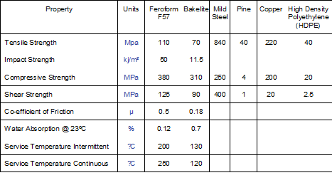 Both F57 and Bakelite sheet can be purchased from Bearing Thermal Resources Pty Ltd: 5 Kerr Court Rowville, Victoria 3178 Australia Telephone: (03) 97642009 Facsimile: (03) 97641009 Email: sales@btresources.com.auInternet: http://www.btresources.com.auIf anyone wants replacement Bakelit or F57 vanes for their Norman, give me a yell. I also have some rotor springs (the new Inconel ones that do not fail like the original carbon steel ones). |
|
|
|
|
Logged
|
|
|
|
|
Harv
|
|
« Reply #283 on: April 15, 2015, 06:45:55 PM » |
0
|
Another issue I had put on the back-burner was the uses of hoses on Norman superchargers. Some of the Type 65/70 Normans have a low mount bracket, where the supercharger sits in the place normally occupied by the grey motor generator. This location requires the supercharger discharge to be connected to the cylinder head (inlet manifold) via a pipe or hose. Similarly, the later Type 75 superchargers used on red motors mounted the supercharger on the drivers side of the engine, and crossed over the rocker cover using hose connections. It is possible to just use rubber hose
but it will not last long, and if it bursts, you have a fuel/air mixture screaming out right near the hot exhaust. The basic specification for the hose is as follows: a) Must be compatible with a mixture of petrol, oil, air and water vapour. Preferably also compatible with ethanol (modern pump fuels
or E85) and methanol. Most modern turbo silicone hose (the stuff you see on modern Zim Pirate intercoolers) is only rated for air, and wont handle the petrol (let alone alky). b) Must be able to withstand a working pressure of 10psi (common Norman discharge pressure limit), and preferably 20psi (a 10psi Norman has a the relief valve set around 15psi
nicer if the valve lifts before the hose bursts). c) Must be able to withstand a working temperature of 120º, and preferably 160ºC. This may be lower with water injection, but better safe than sorry. d) Must be able to withstand a working vacuum of 22Hg. This is because at idle the supercharger discharge manifold is under vacuum. This is the hard part
we are after a combination of a vacuum and pressure hose. g) Assuming you are aiming to use a (relatively standard) inlet manifold, the BXOV-1 throttle body bore is 15/16 (33.3mm). We want a hose with an ID around this size. The above combination is not an easy specification to meet. I did a lot of calling around, including both automotive suppliers and industrial suppliers like Pirtek. Most could not meet the spec. The closest I came was a lined silicon hose from RP Wallis. They do a 32mm hose (SFL32), 90º elbows (SFLE90-32) and 45º elbows (SFLE45-32). They also do 45mm, but that is probably a little too big unless you use a custom manifold. Contact for RP Wallis is as per below: RP Wallis Wholesale Sydney Unit 2/158 Newton Road Wetherill Park, NSW, 2164 Telephone: (02) 9756 5111 Facsmile: (02) 9756 5658 Email: sydenquiries@spareco.com.auAn alternative to using this hose is to use a convoluted (bumpy) hose. This is similar to what Bill Norman did on his Type 65-blown MGTC, and looks more period-correct. A hose that is suitable for this is IRCOSD-938. This is a 38mm ID/63mm OD pipe, rated for 75psi pressure, -380mmHg vacuum and 120ºC. but only 38mm ID. Pipe is 63mm OD. 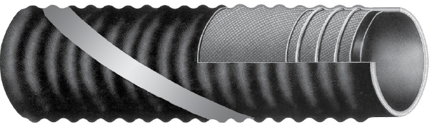 The hose is available from Pirtek: Pirtek Fluid Systems Pty Ltd Telephone:134 222 Internet: http://www.pirtek.com.au/Cheers, Harv (deputy aprpentice Norman supercharger fiddler). |
|
|
|
|
Logged
|
|
|
|
|
Harv
|
|
« Reply #284 on: May 03, 2015, 06:44:11 PM » |
0
|
Ladies and gents, In the post below, Id like to show you the guts of one of the early Norman superchargers. This one sold recently, and the new owner has been kind enough to pass on some cool photos many thanks Ian. Each new Norman I get to look at helps to piece together more of the puzzle, and Ians Norman is no exception. Ians Norman is an early steel-cased Type 65 (one of Eldreds, and similar to Ted Robinettes). The casing is a typical Type 65 with seventeen external casing ribs, seven bridges across the inlet port, eight bridges across the discharge port, and ten bolt holes over each of the inlet and discharge ports. 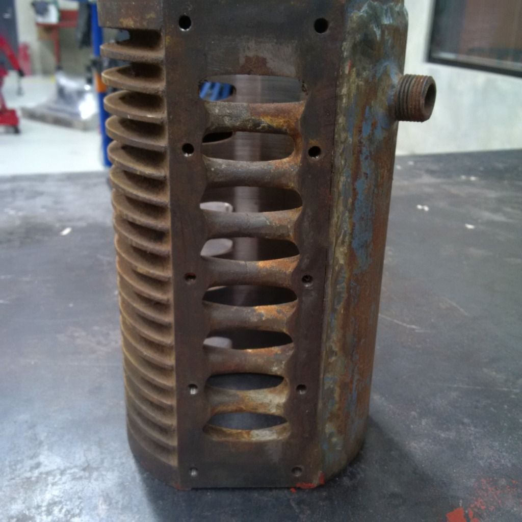 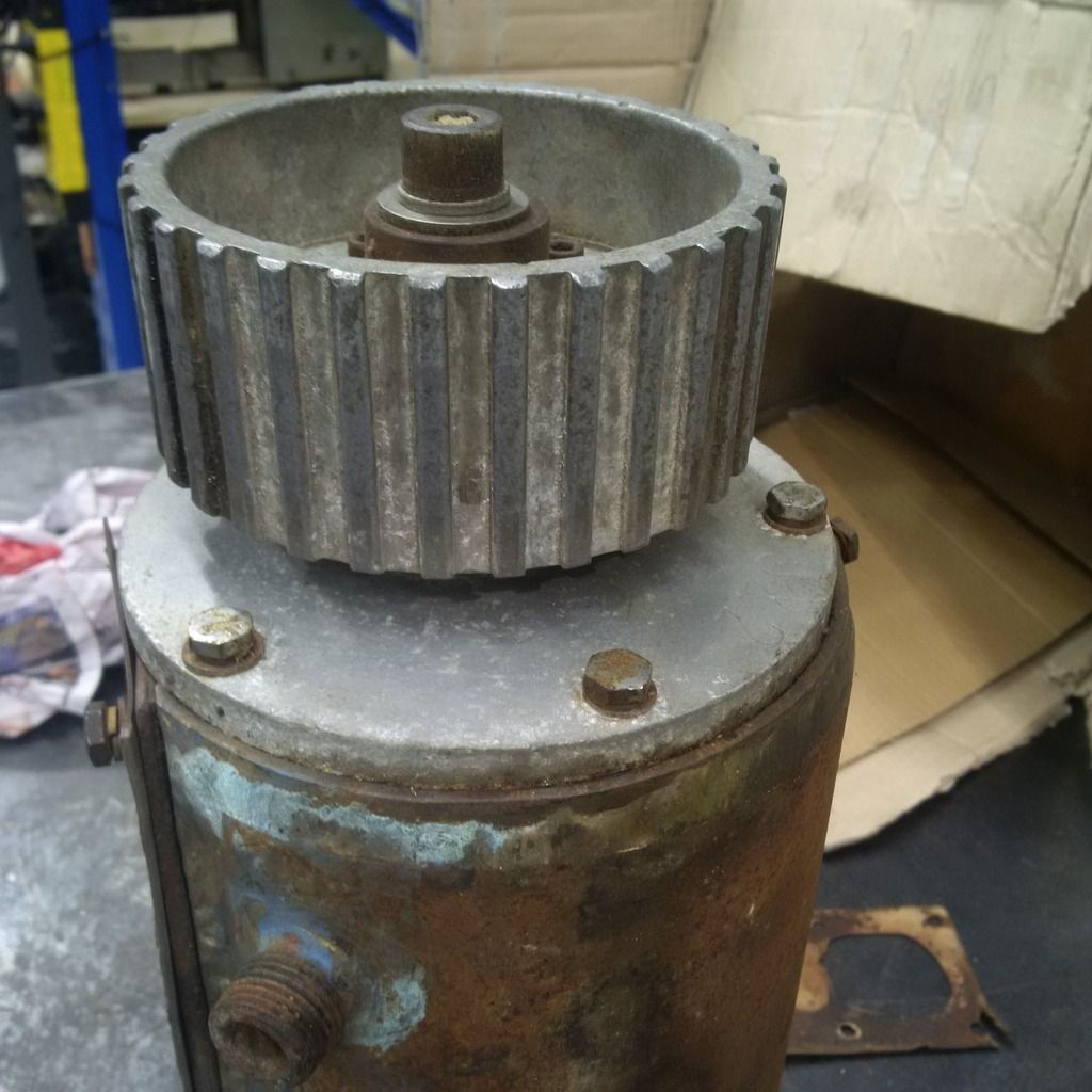 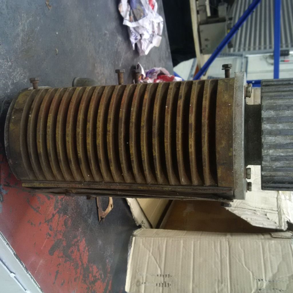 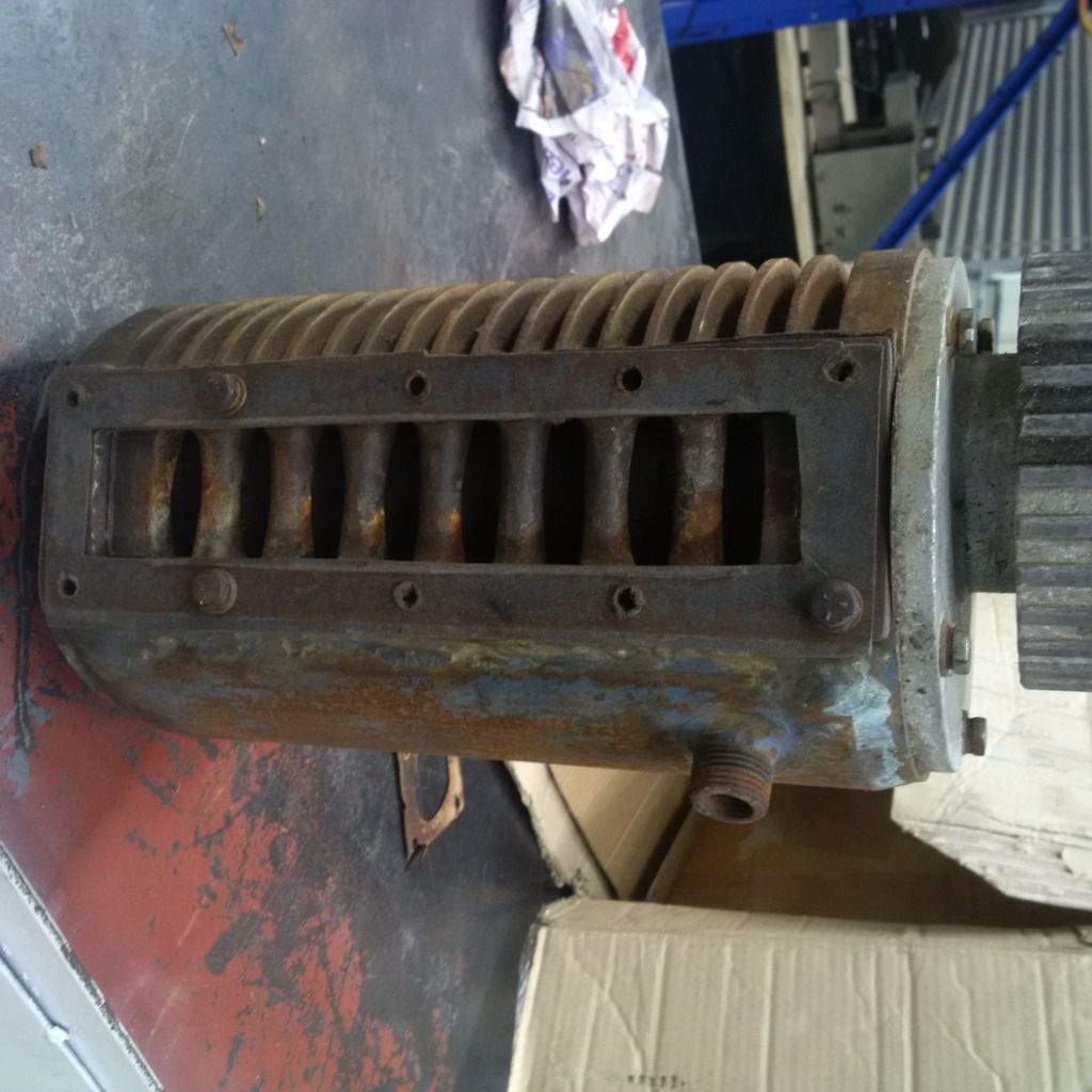 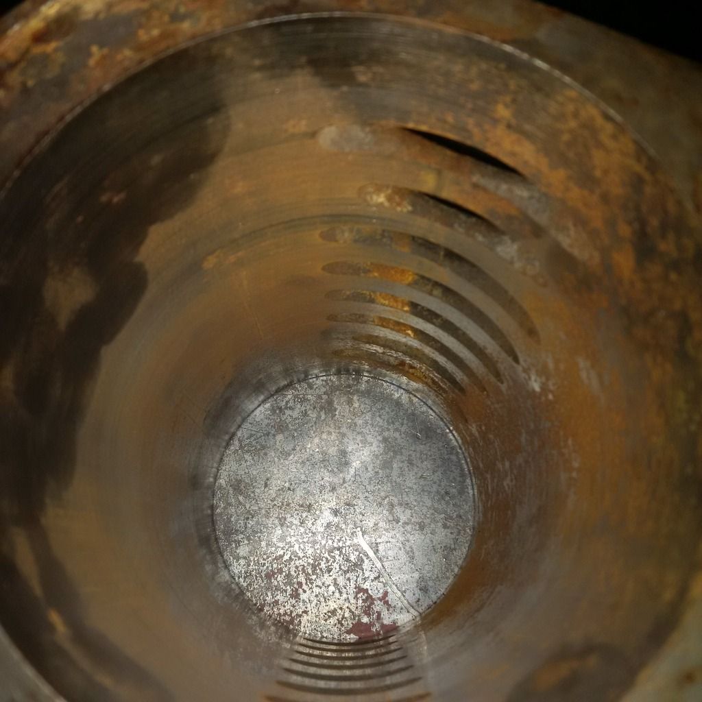 Interestingly, Ians Type 65 has had a water jacket brazed on at some time in the past. This is identical to the water jackets seen on Anthony Harradine and John Browns Type 65s. 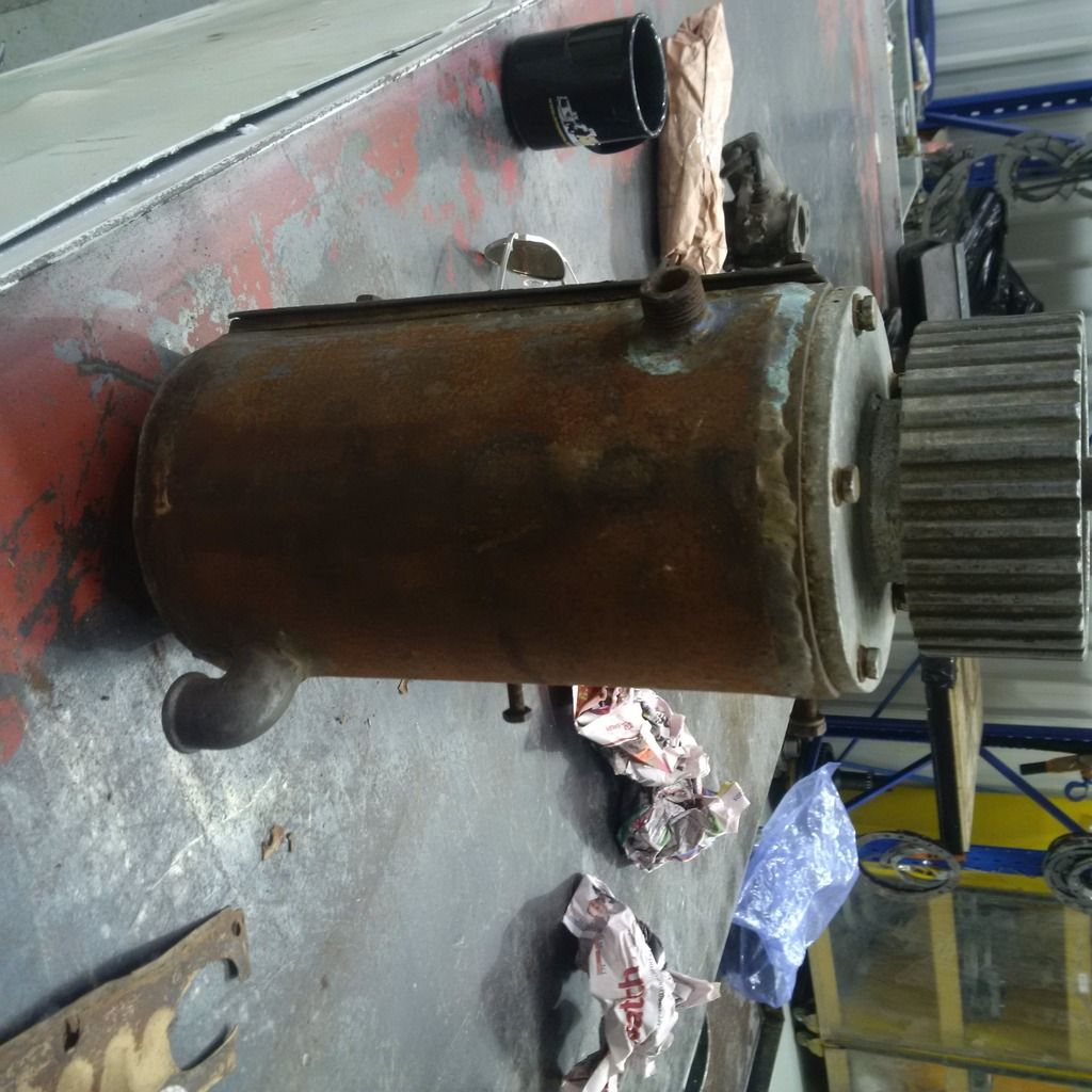 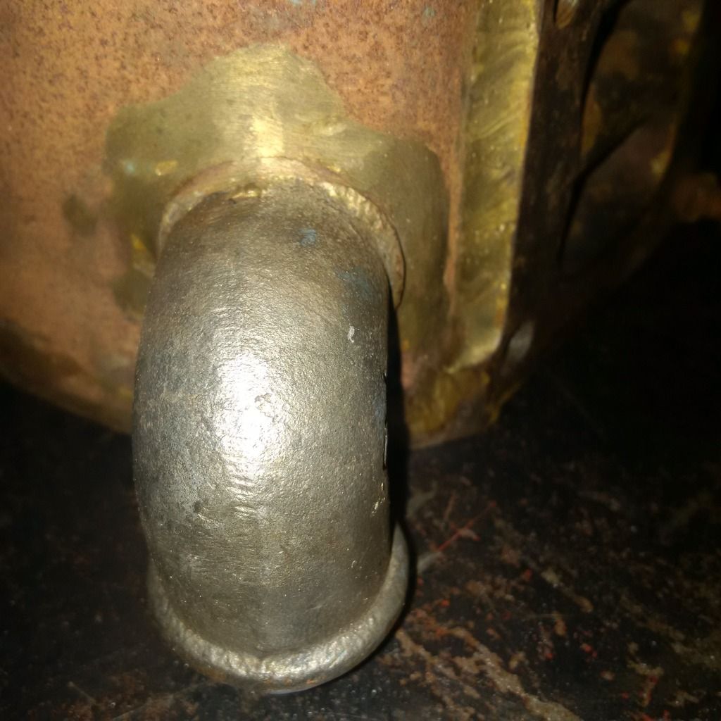 Now that I have seen three identical ones, I suspect that Eldred started out with the steel cased air cooled Type 65s, then moved to the steel cased water cooled Type 65s (by brazing on a cooling jacket), then finally to the alloy cased water cooled Type 65s (like Garys). Notice the shape of the brazed on 90º water fitting (nipple) this is similar to other Normans of that era. There appears to be yellow paint on the outside of the casing. I have seen similar yellow primer/undercoat on other Type 65 Normans. Garys had a layer of this stuff that had stuck like dog poo to an army blanket I had yellow boogers for a week after cleaning it up :lol: . Ians casing shows the circumferential scratches typical of a Norman, and probably wants a hone before putting back into service. The drive end plates look to be cast alloy, correct for any Norman supercharger, and have the five bolt holes as expected, together with a welsh plug in the non-drive end. 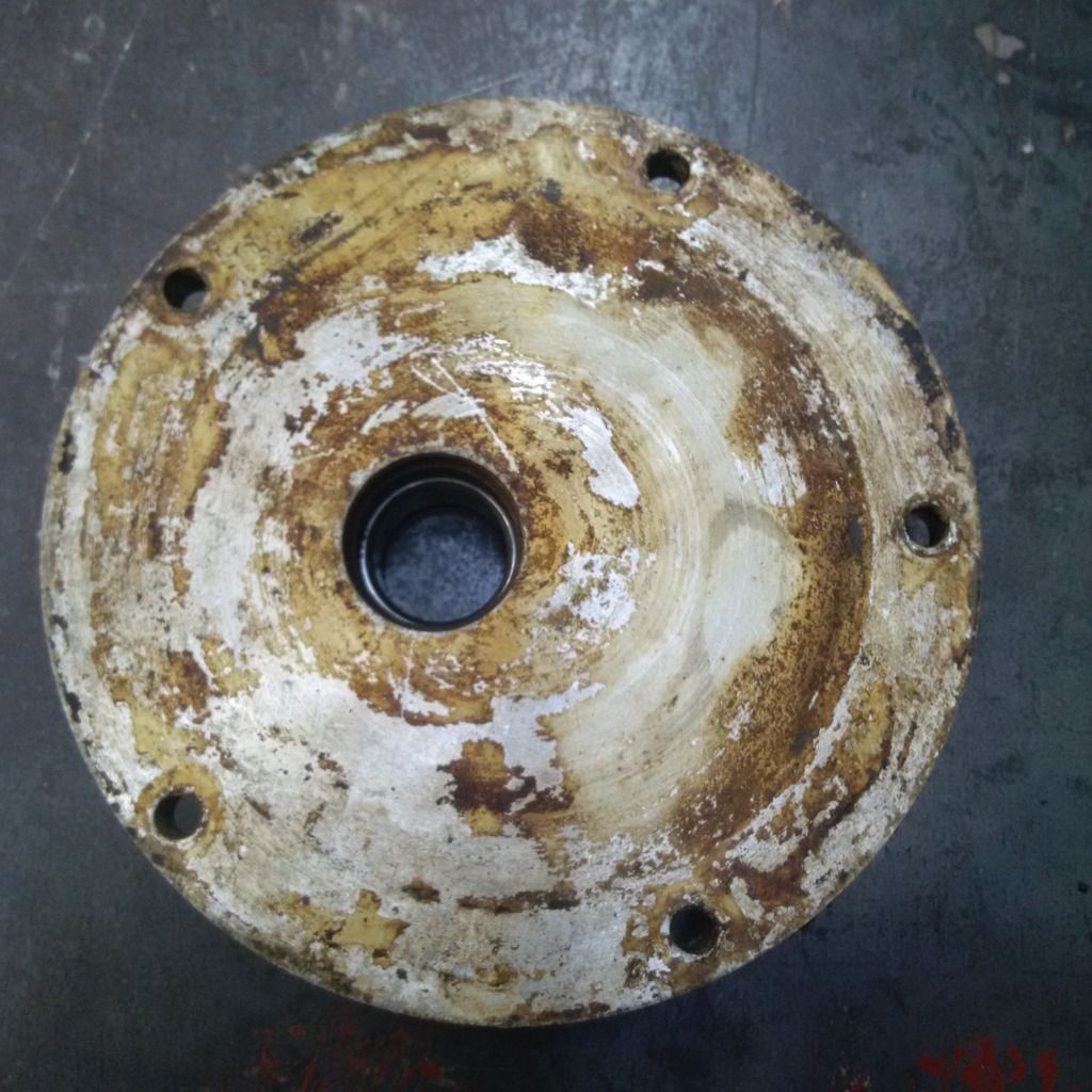  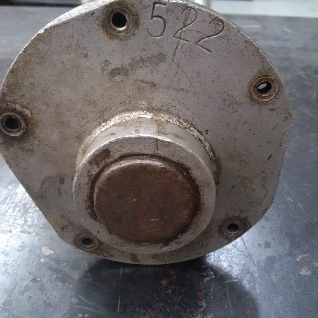 The unusual thing is that there is no Norman cast into the end plates, which both Eldreds and Mikes had. I had at first suspected they were non-genuine end-plates, but a little bit more of the puzzle has since fallen into place. Note the image shown on the brochure below, which is also a Type 65... Interestingly, the drive-end end plate does not appear to have Norman cast into it, nor have the boss cast into it that NORMAN is cast into. 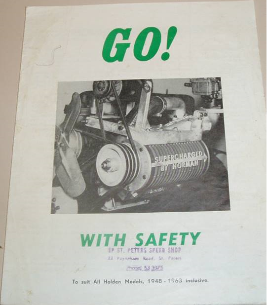 This is just like Ians Norman, and supports my theory that Ians are genuine Norman end-plates. The non-drive end and drive-end stamping (522) is also unusual I havent seen this before. It is definitely not a serial number (or at least not a sequential one), as there were not 500-odd Type 65s made. It could be a numbering sequence that did not start with 1, or it may be a date code (perhaps the 5th of February 1962). |
|
|
|
|
Logged
|
|
|
|
|
Harv
|
|
« Reply #285 on: May 03, 2015, 06:46:02 PM » |
0
|
Ians Norman has the four vane steel rotor typical of Type 65s. 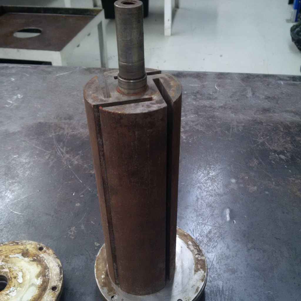 Whilst the fabric inside the vane binder looks right, the colour of the vanes is unusual. The Bakelite used in the early Norman superchargers is normally very dark brown. It could be that a different grade of Bakelite was used, or that the vanes were replaced with the latter Feroform F57 material. One thing to be wary of is if the vanes have been inadvertently replaced with fibreglass, which is also this light colour. Fibreglass is much more abrasive than Bakelite, and can scuff the bore. Type 65 Normans have a threaded nut on the end of the drive shaft, whereas Ians has been shortened, and the end of the shaft (on the left of the photo below) tapped to take an end-keeper set screw. 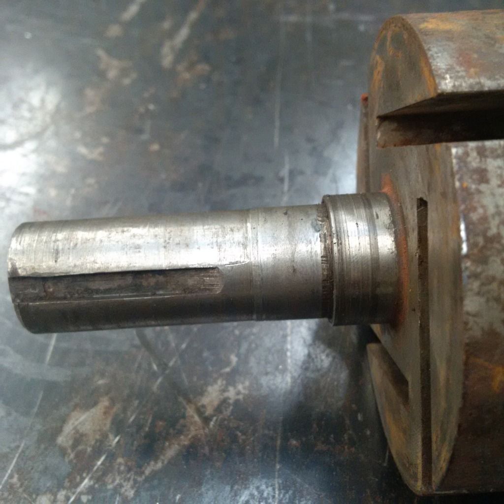 I suspect that this was a normal Type 65 Norman drive shaft which has had the end cut off it, then drilled and tapped for the set screw. This was probably done when the vee-pulley was changed out for the gilmer drive. Ians drive pulley looks to be a 30-tooth trapezoidal profile, heavy-duty (½ pitch) H-belt, attached via a collar onto the shaft, with an interference fit. Interestingly, this Norman has unusual thin shim plates between the rotor and the end plates (i.e. running on the inside of the casing). 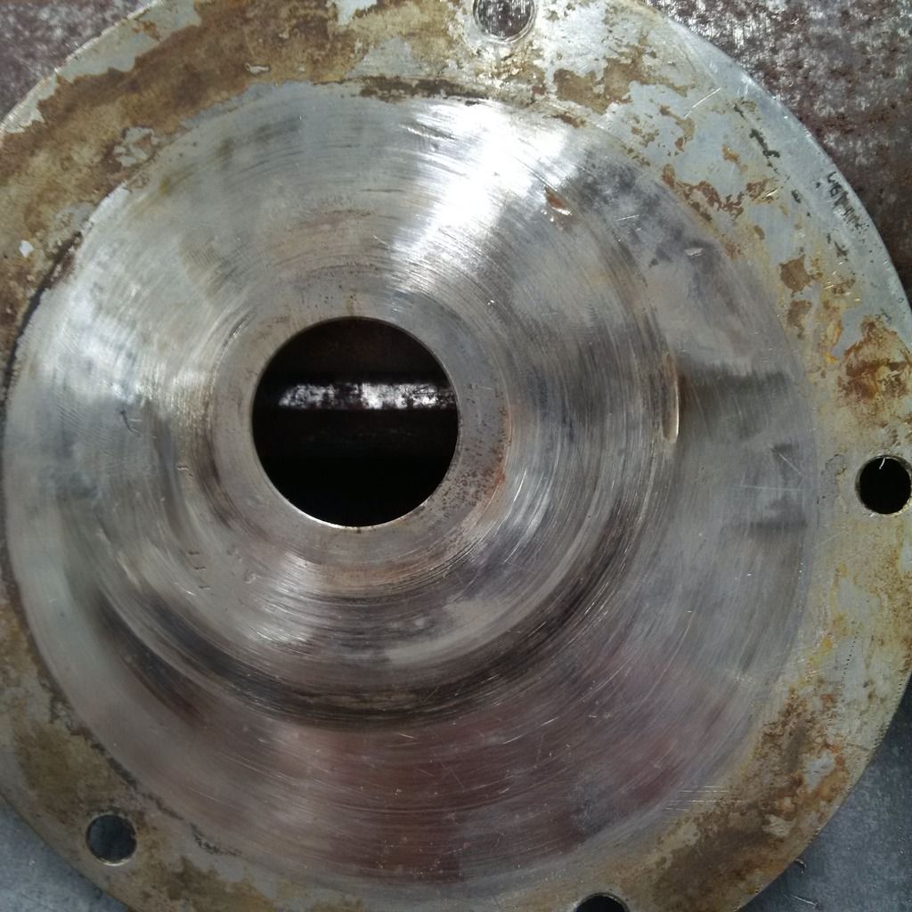 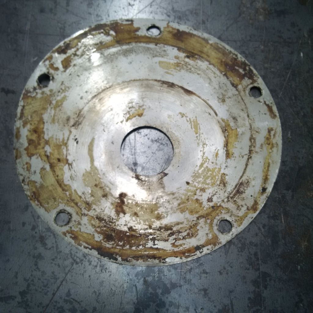 My guess it that it was a normal Type-65 shaft, which originally ran a vee-belt pulley. Someone wanted to change it to gilmer drive, and did not want the tip of the rotor shaft sticking out beyond the gilmer pulley (may have clashed with a radiator). They then cut the threaded end off, fit the gilmer pulley (with its collar), and then drilled the end of the rotor shaft out for the keeper/setscrew. Once the keeper/setscrew was in place, my guess is that they found out that the clearance between the rotor and drive-end plate was huge (much more than 0.010). This would allow a lot of gas to bypass the rotor, and give crappy boost. They then fitted the shim onto the drive-end to reduce the clearance. Looks like it was once held on to the end plate with gorilla-snot contact adhesive (the yellow crap on the end-plates). The problem is, the shim (and layer of contact adhesive) would need to be incredibly flat any warpage would mean it would brush the rotor (remember we are only talking 0.010 gaps). The shim would also be under vacuum (near the inlet) and pressure (near the discharge) at the same time. This pressure difference would almost certainly cause the shim to flex and brush the rotor, causing the marks that can be seen on the shim. The shim at the non-drive end was probably fitted for the same reason to reduce non-drive end clearance. 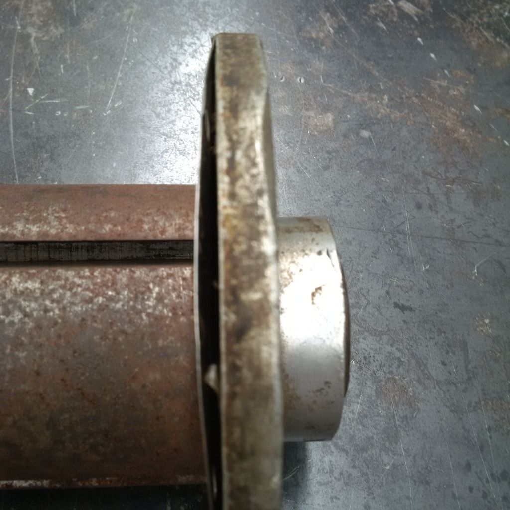 This is not needed, as the non-drive end clearance can be set by changing the end palte gasket thickness(es). The non-drive end however grows as the exchanger gets hot, with the clearance decreasing (this is why the non-drive end is a 2-piece roller bearing that can slip). If they shimmed the non-drive end to a tight tolerance, it would bite every time the supercharger warmed up. Cheers, Harv (deputy apprentice Norman supercharger fiddler) |
|
|
|
|
Logged
|
|
|
|
|
Harv
|
|
« Reply #286 on: May 04, 2015, 01:46:37 PM » |
0
|
Dammit
I made a mistake. I have seen the serial numbers stamped onto the end plates of Normans before. Ted Robinettes air-cooled Type 65 is stamped 513 (and has NORMAN cast into it): 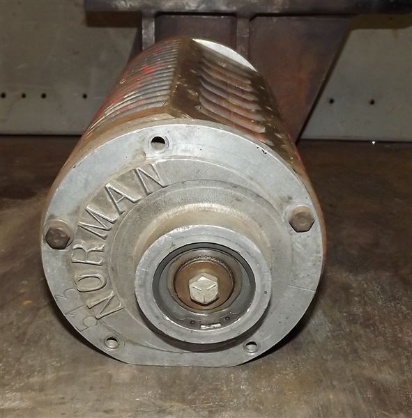 The number is very similar to Ians stamped 522, again reinforcing that the plain end-plates (like Ian's, without Norman cast onto a boss) are likely to be genuine Norman units. Cheers, Harv (deputy apprentice Norman supercharger fiddler). |
|
|
|
|
Logged
|
|
|
|
|
Harv
|
|
« Reply #287 on: May 04, 2015, 02:58:14 PM » |
0
|
While I think of it, some info around the water-cooled alloy Type 65 and Type 70 castings. It looks like all the Type 65 alloy water cooled units had the same casting number (22). Shown below are Pauls Type 65: 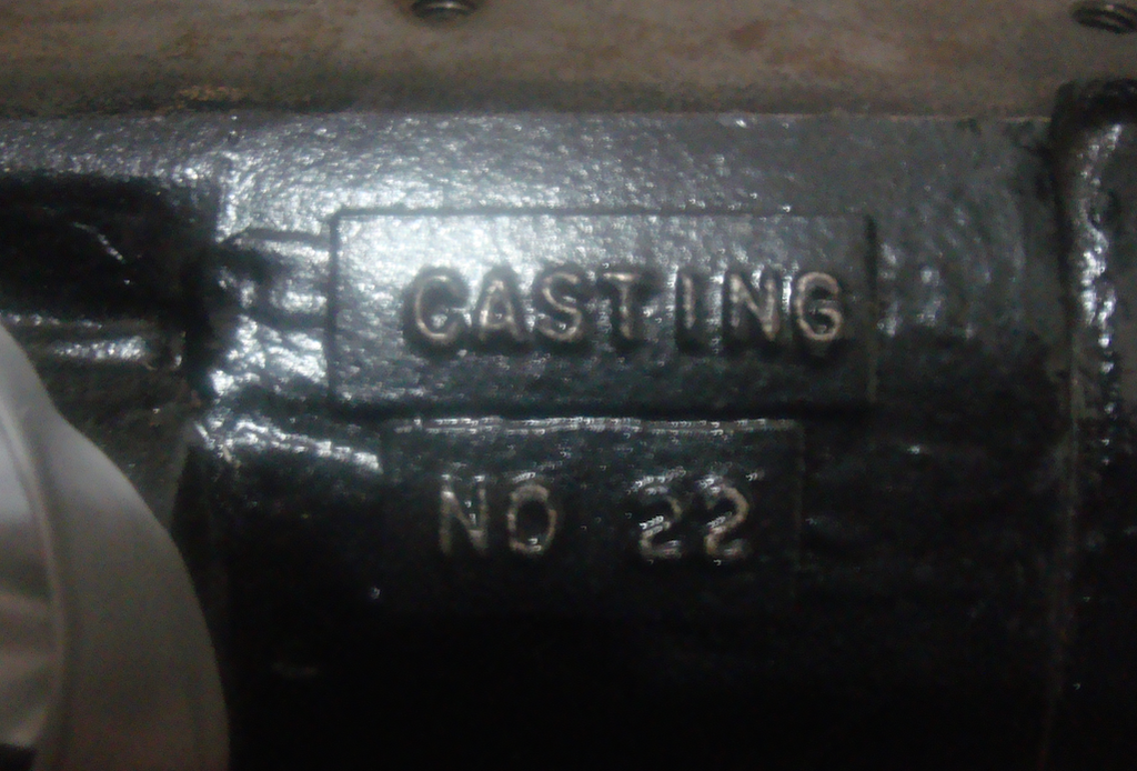 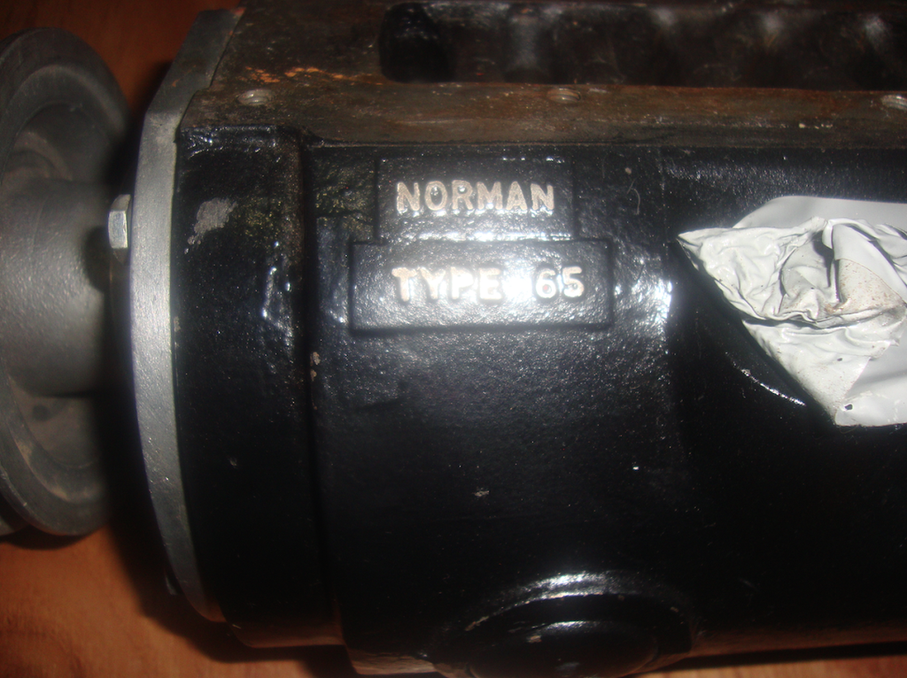
along with Garys Type 65 (also casting number 22): 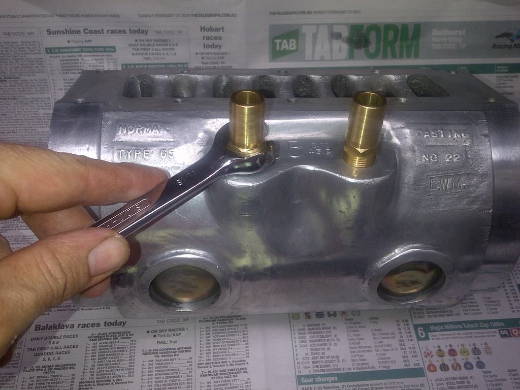 Some of the Type 70s had casting numbers. Peter Wooleys (appears to be 28
or maybe that synonymous 22) 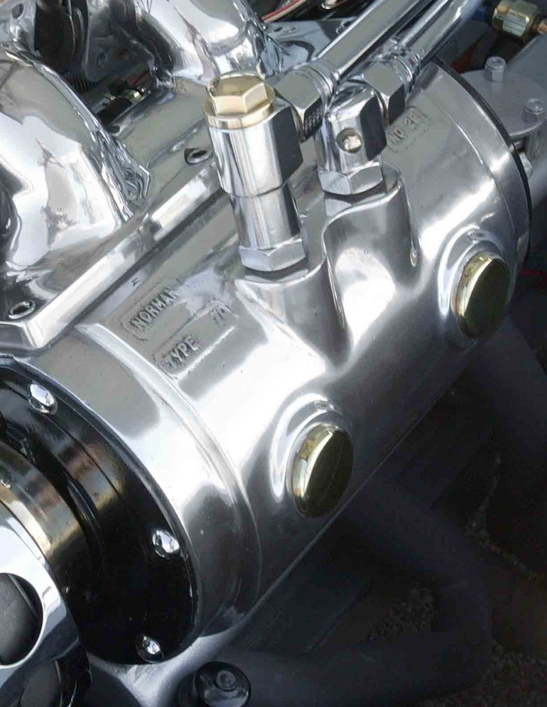
and below the WonderCars Type 70 with no casting number: 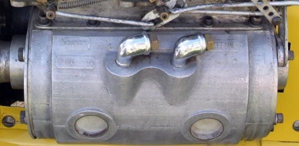 Cheers, Harv |
|
|
|
|
Logged
|
|
|
|
|
Harv
|
|
« Reply #288 on: May 06, 2015, 12:27:05 PM » |
0
|
Some further discussion with the various owners has verified there are in fact at least four different Type 65s:
a) Air cooled, steel casing (Ted Robinettes and Lindsay Wilsons)
b) Water cooled, steel casing with water jacket welded on (Ians, John Browns, Anthony Harradines)
c) Water cooled, steel casing, integral cast jacket (Pauls)
d) Water cooled, alloy casing, integral cast jacket (Garys)
Cheers,
Harv
|
|
|
|
|
Logged
|
|
|
|
|
fcwrangler
|
|
« Reply #289 on: May 22, 2015, 07:51:37 PM » |
0
|
Hey Harv, just found a Norman supercharger on eBay. Add says it's made by the son and is no.4 of 400. It has been set up for a Rotory engine, and the bid is at $1500 odd ( thinking about it).
Jim
|
|
|
|
|
Logged
|
on the seventh day: God Made Holden
|
|
|
|
GreyFC
|
|
« Reply #290 on: May 23, 2015, 05:29:54 AM » |
0
|
I spotted this blower on Facebook for sale. All these people said rare as ect ect providing false info. I asked the one and only for some advice which I shared with the owner. So in fact Harv wrote that add  |
|
|
|
|
Logged
|
|
|
|
|
Harv
|
|
« Reply #291 on: May 23, 2015, 07:55:11 AM » |
0
|
Yep, it gave me the giggles when I saw my answers written into the eBay ad. All's good though - happy to help provide some decent info.
Cheers,
Harv (chief eBay ad ghost-writer extraordinaire).
|
|
|
|
|
Logged
|
|
|
|
|
Harv
|
|
« Reply #292 on: July 10, 2015, 06:10:26 PM » |
0
|
A bit of an update on Ian's Type 65, which I described above. Remember that Ian started out with a typical "been under the bench for years" Norman that looked like this: 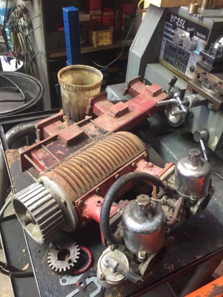 He's since finished the strip down, and had the drive end pulley bolt hole drilled and re-tapped on centre. Along with some new bearings and a clean-up, I've sent him some new Bakelite vanes, and some mighty thin gasket sheet to set the non-drive end clearance. Sadly, his drive-end end plate had a crack in the seal area. He has bitten the bullet, and had new drive-end and non-drive end plates machined up: 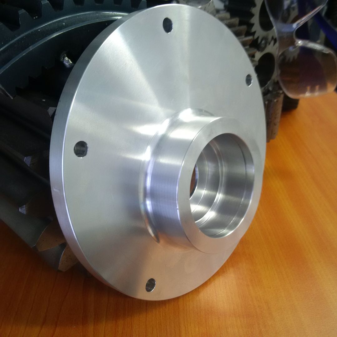 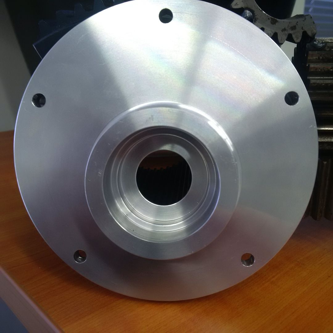 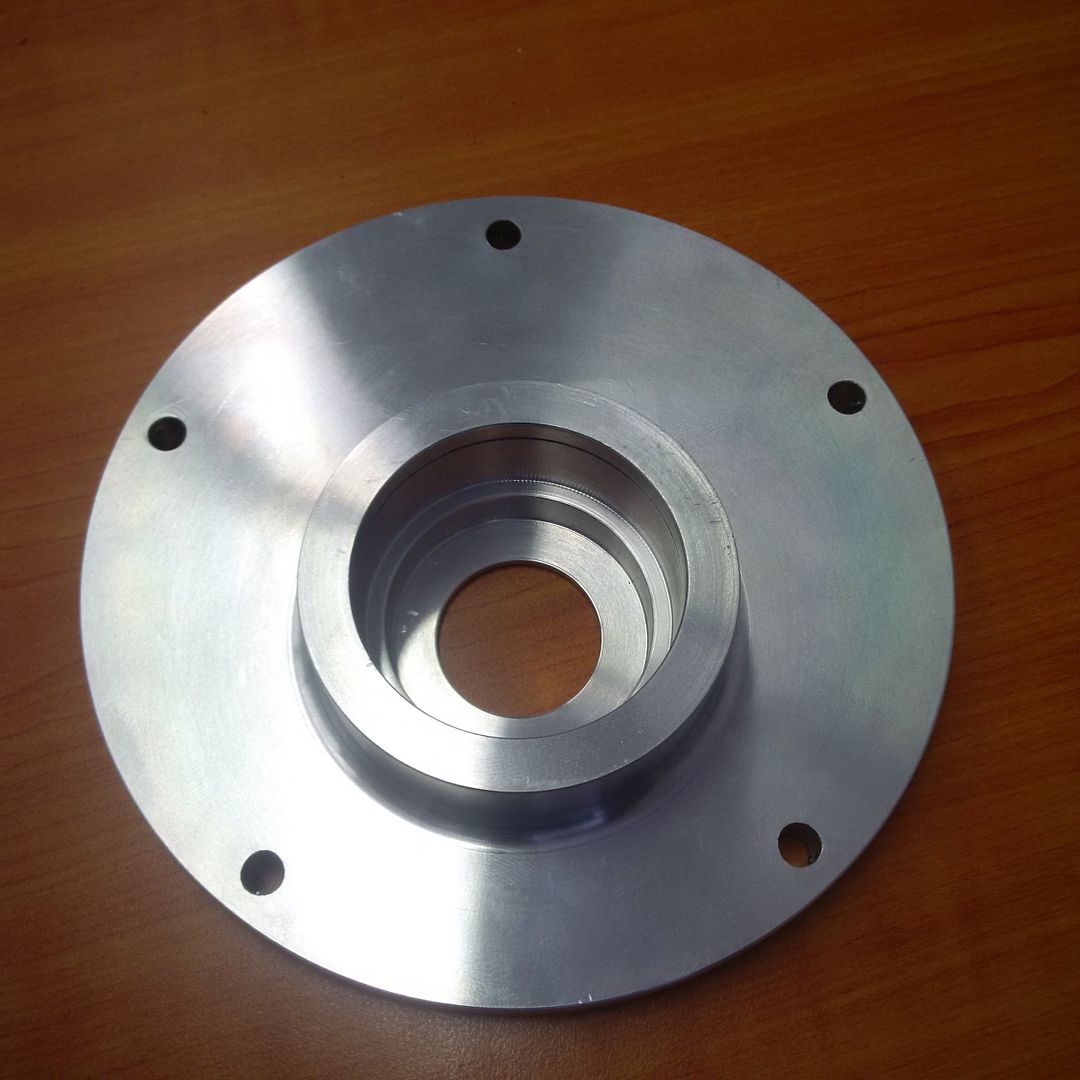 This is about as close to Norman porn as you can get :mrgreen: . Gotta love machinists who can do off-centre turning. In the mean-time, I've nearly got Gary's 350 Norman finished... just gotta lap-in the new F57 vanes. Cheers, Harv (deputy apprentice Norman supercharger fiddler). |
|
|
|
|
Logged
|
|
|
|
|
Harv
|
|
« Reply #293 on: September 25, 2015, 06:21:30 PM » |
0
|
I got reminded by Mike that this year marks the 51st anniversary of the Norman supercharged Elfin, operated by Andrew Mustard and Mike McInerney setting the following Australian national records:
the flying start kilometre record (16.21s, 138mph),
the flying start mile record (26.32s, 137mph), and
the standing start mile record (34.03s, 106mph).
The vehicle falls into the FIA Category A Group I class 6, with the record set at Salisbury, South Australia on October 11th, 1964. These records stand in perpetuity (i.e. they can no longer be challenged under CAMS rules).
This October long weekend also marks the 50th anniversary of Mikes attempt (in twin-Norman supercharged guise) to pursue the standing ¼ mile, standing 400m and flying kilometre records (October 1965). Sadly, the twin-Norman supercharged Elfin no longer holds those records, as the ¼ mile and flying kilometre (together with a few more records) were set at this time by Alex Smith in a Valano Special.
Happy Golden Jubilee, Mr McInerney.
Regards,
Harv
|
|
|
|
|
Logged
|
|
|
|
|
Harv
|
|
« Reply #294 on: September 26, 2015, 06:45:25 PM » |
0
|
A cool advertisement from Australian Hot Rod of December 1969 (with thanks to Alex):  Cheers, Harv |
|
|
|
|
Logged
|
|
|
|
|
Harv
|
|
« Reply #295 on: October 31, 2015, 03:31:00 PM » |
0
|
|
|
|
|
|
Logged
|
|
|
|
zulu
nsw-club
Guru

 Offline Offline
Model: FE and FC
Posts: 1860
Old Boonah Ambo

|
|
« Reply #296 on: November 01, 2015, 11:35:45 AM » |
0
|
Well, this is not FE FC related but I now have my very own red motor, albeit shagged, so this Norman may one day find its way onto it It's sort of a Mad Max meets Ghost Busters old ex Ambo   Plan with this is to just get the mechanicals done so I can drive it, but I don't want to change it's appearance too much, just the essentials and remove the rat dung and snake skins If anyone out there has a vacuum cleaner and a strong reliable red 186 or 202 for sale let me know  Cheers, Gary |
|
|
|
|
Logged
|
|
|
|
|
Harv
|
|
« Reply #297 on: November 26, 2015, 08:24:29 PM » |
0
|
Ladies and Gents, As I was overhauling Garys 350 Norman, I took detailed notes and photos to send to him. Ive finally had some time to trawl back through my notes and pull out some of the learnings. The post below covers them, albeit in no particular order. When the original vanes were pulled from the Norman, it was apparent that they had started to suffer from delamination. The photo below shows two of the vanes, with the delaminations highlighted by the match heads. 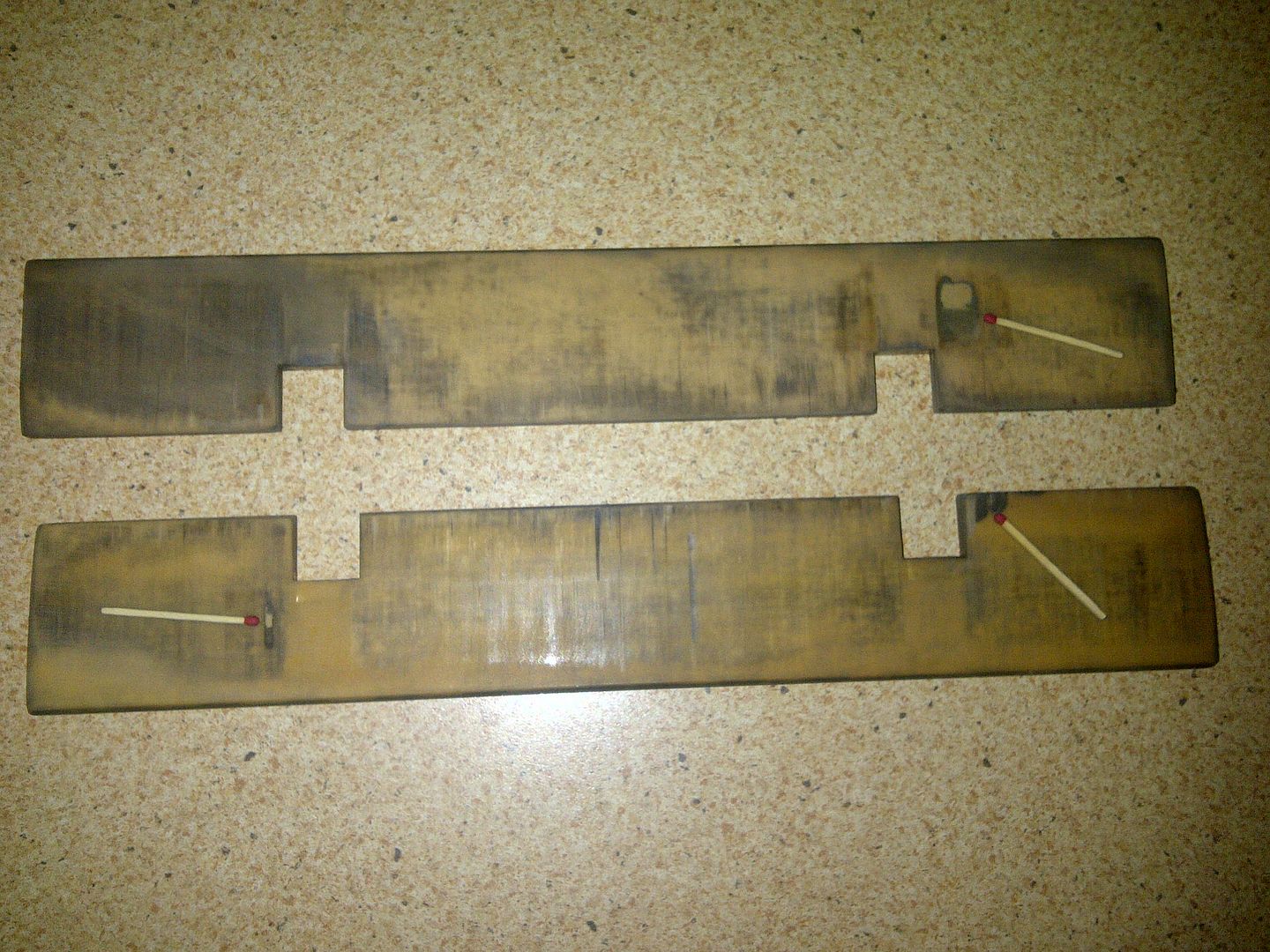 For replacement vanes, I got hold of some F57 (a Bakelite replacement which we have discussed before). The photo below (from top to bottom) shows the original Norman vane, an F57 vane cut to size, the F57 vane blank and a Bakelite vane blank. 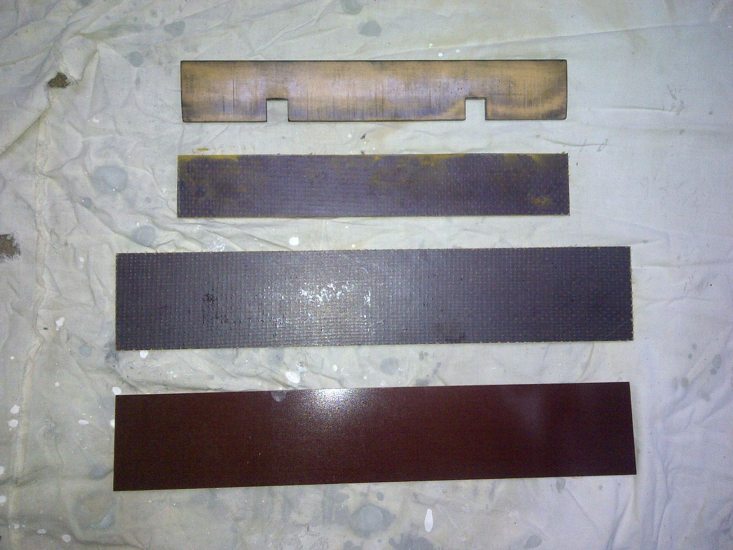 Note that I now have a stockpile of both F57 and Bakelite vane blanks. They are large enough that they will suit all Normans, with the exception of the Type 270, Type 265 and perhaps Type 90 (never had one of these three apart). If anyone wants some, give me a yell. I also have the replacement Inconel valve springs that prevent spring shattering. I started by cutting them the F57 blank length (see diagram), going slightly oversized. 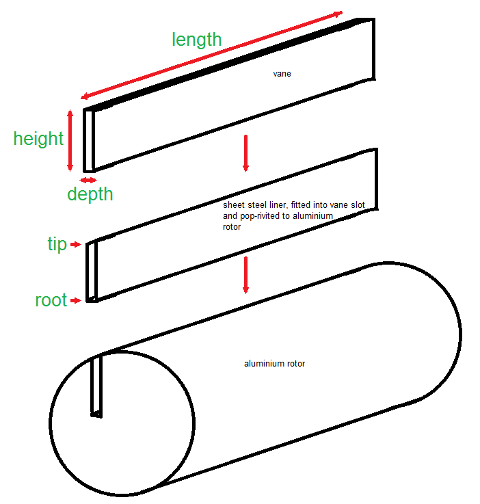 This is a short length of cut, and easy to do with a hacksaw. The length needs to be then lapped down so that the vanes are exactly as long as the rotor. I held off lapping until the vanes were trimmed for depth. The next cut I needed to make was for height. This is a looooong cut, and a hacksaw would give a very wobbly finish. This needs to be fairly straight, as it provides a flat scraping/sealing surface against the casing wall. To do this, I put the angle grinder into a drop-saw jig, and set up a fence to run the vane along. This gives a nice, parallel and neat cut. 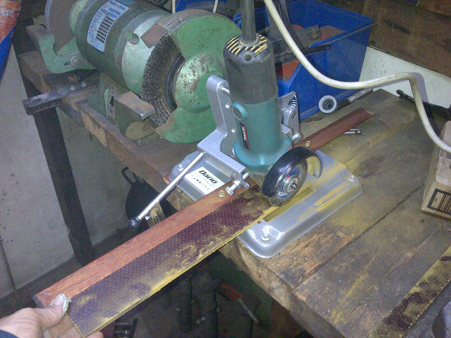 The final "cut" I needed to make was for depth. This is done by lapping the vanes down on lapping plates, aiming for a flop fit in the rotor. Ive made up the lapping tool to do so (see drawing) out of some angle iron. 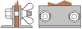 The superchargers made by Mike Norman have steel liners pressed into the vane slots and riveted in place. Interestingly (
maybe frustratingly), the resultant vane liner slot is nowhere near parallel. The root of the slot is narrower, whilst the drive end overall depth is narrower than the non-drive end. This makes the lapping a fun process as the vane is rubbed against the lapping plate, you need to bear down slightly harder on the areas that need to be less deep. I was lapping with 80 grit paper, and spent quite some time on just one vane the Kevlar reinforcing is softer than the sandpaper, but still resistant to being abraded. In the end, I went back to P40 paper, then smoothed out with finer grades. |
|
|
|
|
Logged
|
|
|
|
|
Harv
|
|
« Reply #298 on: November 26, 2015, 08:25:07 PM » |
0
|
Having got the vanes sized correctly, I lapped down the length dimension - fit to rotor, check how much the vane hangs out, lap it down, repeat... a lot. With the dimensions finalised, I cut the spring notches and ground the relief grooves on the back of all three, using a diegrinder then flat file. The relief grooves are oriented on the downstream (low pressure) side of the vane. This configuration allows the vane slot root to vent. As the vanes operate in an oil film, there is a chance that the vanes form a seal in the vane slot, and either draw a vacuum at the vane root when sliding out, or build pressure at the vane root when sliding in. The grooves allow the vane root to vent, preventing the vane sealing with oil and not being able to rise/fall in the vane slot. An alternative way would have been to machine the relief grooves on the upstream (high pressure) side of the vane. The theory in that type of location is that higher pressure air/fuel can get under the vane and lift it, increasing vane seating pressure and getting a better seal. I have not seen this configuration put into place in Norman superchargers, but have heard of it being done for some Wray superchargers. The finished vanes are shown in the image below, along with the original Norman vanes. 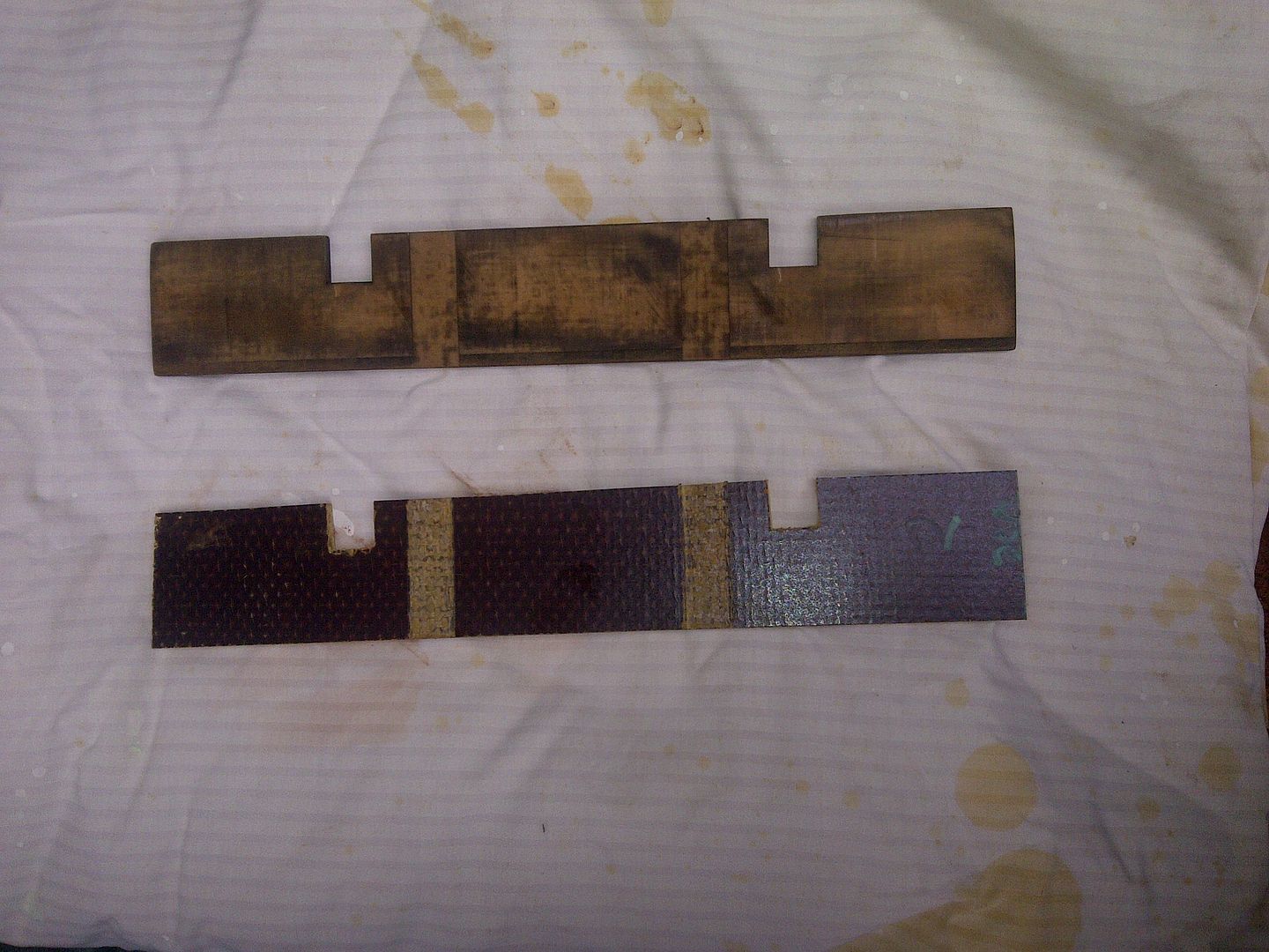 Another lesson learnt on the 350 Norman relates to the end-plate gaskets. None of the Normans made by Mike Norman that I have pulled apart have had these gaskets (whilst Eldredd did). The gaskets seal the end plates to the casing. They also provide a means of setting non-drive end clearance, by varying gasket thickness. In the case of Garys 250 Norman, the non-drive end clearance was sufficient that gasekts were not required to increase clearance. To seal the end plates to the casing, I used a thin bead of sealant in the groove that exists for exactly that purpose (even if we used gaskets, I would still add the sealant). This is very different to Eldreds Normans, which have no groove and needs some form of gasket to seal. I used a fine bead of Permatex Ultra Black sealant in the sealing groove. This is a highly flexible oil resistant sealant, good for up to 260°C (intermittent) service. 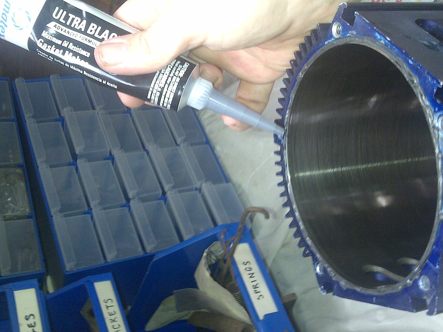 |
|
|
|
|
Logged
|
|
|
|
|
Harv
|
|
« Reply #299 on: November 26, 2015, 08:26:19 PM » |
0
|
In some of Mikes Normans a long drive shaft was ordered by the customer. This allows the supercharger to be mounted further back along the engine and still line up with the crank pulley. The longer drive shafts were fitted with a support assembly, indicated by the arrow in the diagram below: 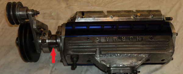 The shaft support assembly fits over the drive shaft between the end plate and the driven pulley, and is fastened onto the end plate by set screws. The intent of the shaft support is to provide a location for the belt tensioner to mount the photo above shows the belt tensioner clamped in place over the tensioner. The drive shaft spins, but the shaft support remains static, with the belt tensioner clamped over it. In the image above, to the left of the red arrow The image below shows Garys shaft support. 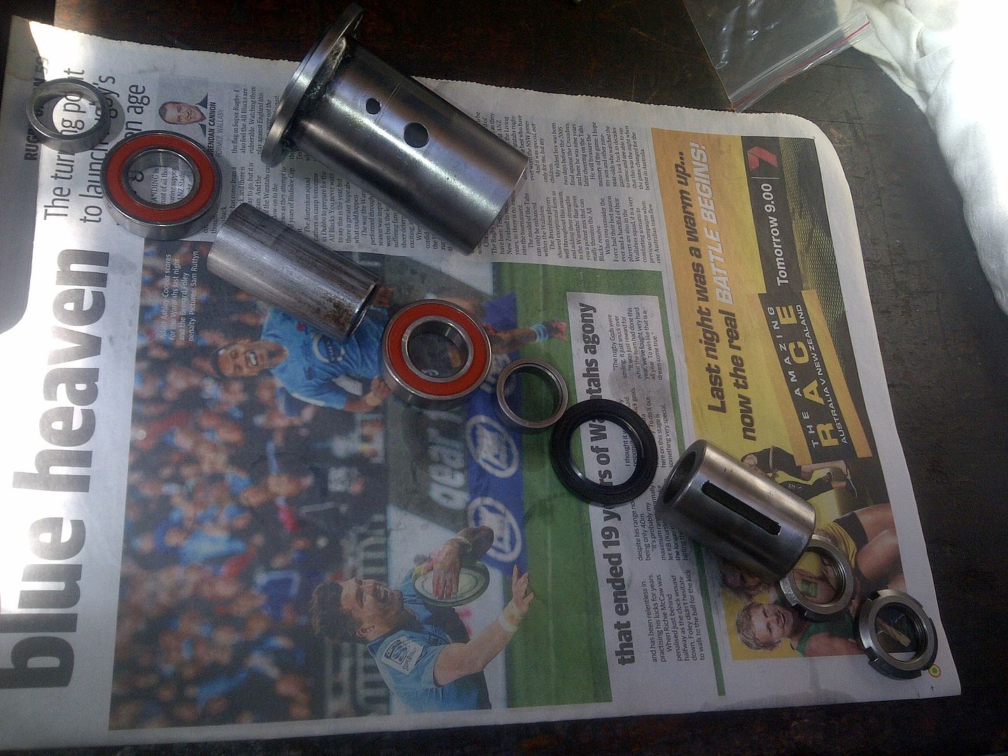 From left to right on the newspaper: a) A mild-steel ring. One side pushes up against the supercharger drive-end bearing, the other is pushed on by the inboard shaft support assembly bearing. b) The inboard shaft support assembly bearing. This allows the shaft to spin whilst the idler pulley arm remains static. c) A long mild-steel spacer. One side pushes up against the inboard shaft support assembly bearing, the other side is pushed on by the outboard shaft support assembly bearing. Notice that above this spacer in the photo is the shaft support itself. It runs on the outside of the bearings, with the long mild-steel spacer running inside it. d) The outboard shaft support assembly bearing. e) A second mild-steel spacer. One side pushes up against the outboard shaft support assembly bearing, the other side pushes up against the drive pulley hub. f) The greaser seal. This is designed to keep grease inside the shaft support. g) The drive pulley hub. One side pushes up against the second mild-steel spacer, the other is held in place by the jam nuts. The drive pulley hub mounts the drive pulley. h) The jam nuts. These push the whole assembly together and are installed on the end of the supercharger shaft thread. Note that these are castellated nuts, and need a hook-spanner to get them off. The shaft support has a grease nipple fitted to it (in the little hole in the photo above, though absent from the photo). It also has a grease relief valve, fitted into an aluminium grease ring that slides over the shaft support. The grease ring is sealed to the shaft support by o-rings, and is fed grease from the shaft support through the big hole in the photo above. The basic lineup (without any shaft spacers) is shown below: 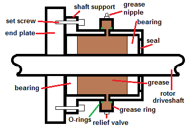 The intent is to pump grease into the annulus between the long mild-steel spacer and the shaft support where my finger is sitting in the photo below. 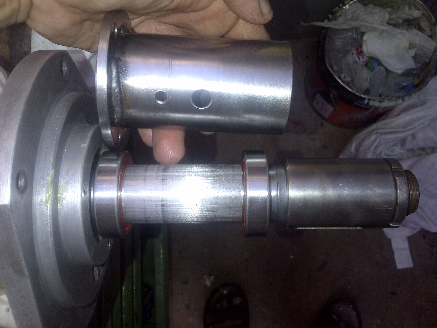 The grease then runs left and right along the shaft, and into the inboard and outboard bearings where those orange bits are in the photo above. Any excess grease pressure then vents out the grease relief valve. This prevents the grease gun from pressuring up the annulus, and bending the crap out of the bearing inner races (bear in mind that a grease gun can exert incredible hydraulic pressure
15,000psi). Note that this only greases the shaft support bearings, not the supercharger bearings. Of note, the modern bearings I have fitted to Garys Norman are sealed. In the photos above, you can see orange rings on the bearings. These sealing rings keep grit and crap out, and the bearing grease (installed at the bearing factory) permanently in. This means that there is no need for regreasing, and that the shaft support grease nipple and relief valve are redundant. Cheers, Harv (deputy apprentice Norman supercharger fiddler). |
|
|
|
|
Logged
|
|
|
|
|


