|
Harv
|
 |
« Reply #180 on: May 26, 2014, 09:48:19 AM » |
0
|
The rotor slot sleeves in Mikes superchargers were originally pressed to shape, Tufftrided, inserted into the rotor then steel riveted using an extension. The fixing method was later changed to punching (expanding) the rivets in using a pointy-ended drift. Mikes rotor springs were typically replaced after 5-8000km of driving. Running without the springs is rattly but does not drop performance. Tufftiriding was used by Mike over nitriding as it provides better anti-galling, was more wear and fatigue resistant and softer (easier to form). One issue to note however in running oil in fuel is that a significant proportion of the oil will condense in the cylinder and end up in the sump (i.e. Norman superchargers can make oil). Experience shows that approximately 80% of the added oil ends up in the sump in this manner. Andrew Mustard (the gentleman with the Norman supercharged Elfin from my earlier anecdote) made some (albeit very few) of his own vane type superchargers with cast alloy rotors. Mikes superchargers sold for around $1000 bare. Mike had cast around fifty Range Rover V8 supercharger manifolds, though only around 15 were sold. I missed one version of the Type 65 supercharger. In previous posts I indicated that the Type 65 was either air cooled/steel cased, or water cooled/alloy cased. There was a third type, presumably made in between the two, which were water cooled/steel cased. I had thought that these were a one-off that someone had home-made by re-jacketing a Type 65 (kinda like my Type 110 had been) until I reviewed my notes and realised there were a few of them. The water cooled, steel cased Type 65s have aluminium end plates and steel rotors. They do not have welsh plugs, and have water nipples not close to each other (one on the rear of the supercharger on the passengers side, and one towards the front of the casing). The first of the two survivors that I know of is the supercharger from the Bobcat FJ custom. This vehicle was built by South Australias Bob Moule, with the magazine clippings shown below from Wild Wild Bobcat article in The Australian Hot Rodding Review of June 1968. 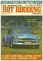 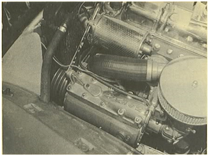 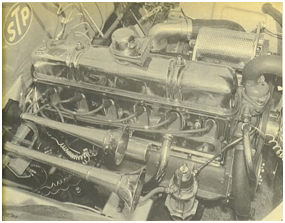 Bobcat was running 5psi boost on a relatively standard FJ grey motor. Note that the mounting here is low, with the generator mounted near the cylinder head and a hose used to connect the supercharger discharge to the standard grey motor inlet manifold. Triple v-belts are used to couple the drive the supercharger, crank and water pump with one belt also wrapping the generator. Both the generator and the supercharger are pivoted, with the combination of the position of the two providing belt tension). The motor was fitted with a Holley 94 carburettor from a Ford V8, which has the same flow capacity as the original BXOV-1 Stromberg (162CFM@3Hg). The engine had Bedford truck valve springs, no vacuum advance, Speco headers and twin exhaust pipes. All up the modifications had increased the grey motors power from 60BHP to 82BHP. This supercharger was removed from Bobcat, and was subsequently fitted to Anthony Harradines EJ Holden Premier (see photo below).  The second of the two survivors that I am aware of was owned by EKDave (from the FB/EK and FE/FC forums) and is pictured below. Note that this machine also has the hose to standard inlet manifold connection. 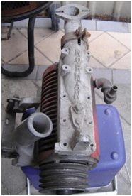 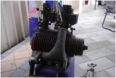 Cheers, Harv (deputy aprentice Norman supercahrger fiddler). |
|
|
|
|
 Logged
|
|
|
|
|
Harv
|
|
« Reply #181 on: May 31, 2014, 04:35:13 PM » |
0
|
In a previous post I wrote an anecdote relating to the use of Norman superchargers on an Elfin sports car. The Elfin had been used for land speed record trials in both single and twin-Norman blown configuration. Whilst researching other material, I stumbled across the two articles below, which I thought Id share. The first article and accompanying photograph comes from The Canberra Times, Saturday the 26th of September 1964, page 28 Elfin in Attempt on record 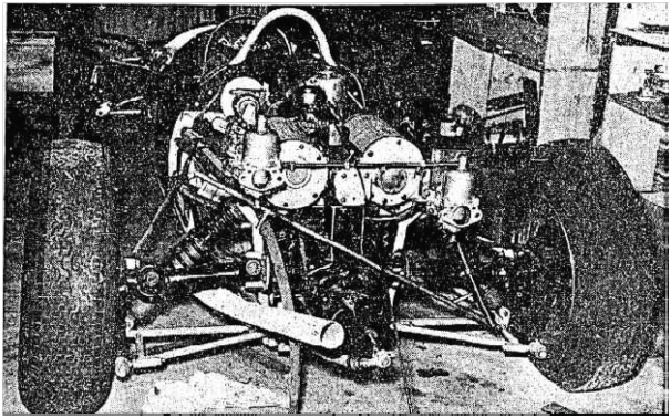 The Elfin racing car originally used to test the surface of the salt track used in the successful attempt on the land speed record by Bluebird will attempt to break the 1500c.c. international standing mile and standing kilometre records. The record attempt will be staged on a recently completed sealed road at the Weapons Research Establishment at Salisbury, South Australia. Mr. Andrew Mustard, project co-ordinator in the recent successful attempt on the land speed record at Lake Eyre, will make the attempt. The car, built and designed by Mr. Gary Cooper, of Edwards town, South Australia, has been timed at 146 m.p.h. in a much detuned state. Extensive work has been done on the car since this time was recorded and Mr. Mustard feels sure that the car is capable of a much higher performance. The car has been modified from its original form for the record attempt. Originally it had a 1,500c.c. Ford Cortina engine, and developed approximately 120 b.h.p. With the fitting of two individual Norman superchargers parallel to each other with each one feeding two of the cylinders, over 200 b.h.p. should be developed. With an all up weight of 850 pounds and 200 b.h.p., the car (pictured above) should have staggering acceleration. As was shown by the Bluebird record at attempt, there are many factors that can set any record attempt off balance. Factors lo be taken into consideration are whether the car will be ready in the short amount of time the mechanics have to work on it, whether the Elfin, with its conventional parts, will be able to stand the strain from the enormous thrust of the 200 b.h.p. for the 10 seconds or so during the attempt, and the most important factor in any record attempt, the weather. The second article comes from the same newspaper, from Monday the 28th of September 1964, page 3 Mustard fails in world land speed attemptADELAIDE, Sunday. Andrew Mustard, team manager and project coordinator in the successful attempt on the land speed record at Lake Eyre by Donald Campbell ,in the Bluebird, failed in an attempt to break the 1500 c.c. international standing mile and standing kilometre records this weekend. He will, however, claim at least two Australian records, subject to official confirmation. They are the formula F flying mile record (at 136 m.p.h.) and the flying kilometre (138 m.p.h.). Mustard made the record attempt on a recently completed sealed road at the Weapons Research Establishment at Salisbury, South Australia, driving the Elfin racing car used originally to test the surface of the salt track at Lake Eyre for the Bluebird attempt. Bad weather and cross winds affected the result in Mustard's attempt. His top speed was over 155 m.p.h. Cheers, Harv (deputy apprentice Norman supercharger fiddler) |
|
|
|
|
Logged
|
|
|
|
|
Harv
|
|
« Reply #182 on: June 02, 2014, 11:56:00 AM » |
0
|
Ladies and gents, A quick post to update my Norman-supercharged speedcar anecdote, following some excellent feedback from Ian Gear (who currently owns the SA#2 WonderCar). This update ties down the origin of the two Rowe Renault midgets. Following the sale of the Norman-supercharged, Peugeot engine SA#2 WonderCar to Joe Braendler, Alex Rowe had the funds to build another Norman-supercharged car for Wigzell, with all new running gear. The first Norman-supercharged Rowe Renault started out with a Peugeot motor, followed by a Renault motor (firstly carburettored, and later injected). The first Rowe Renault was bought by Cec Eichler and was raced under the Kevin Fischer of Murray Bridge South Australia banner alongside the Suddenly #88 Supermodified sprintcar. The Norman-supercharged midget was also numbered #88 and painted in similar purple as the Suddenly #88 car see the image below from my previous post of the two vehicles. The midget had been fitted with fuel injection by this stage and was looked after by Fischer mechanic Ian Thiele. 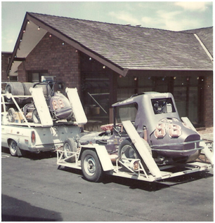 In the mean time (1972) Rowe built another Norman supercharged Renault-engined car using a secondhand Edmonds chassis. The second Rowe Renault (also numbered SA#2 like the WonderCar) was driven by Greg Anderson until the closure of Rowley Park in 1979. Anderson drove the second Rowe Renault to win the South Australian Speedcar Championship in the 1973/1974 season, up against Wigzell in the first Rowe Renault (SA#88). Cheers, Harv (deputy apprentice Norman supercharger fiddler and historic Speedway appreciator). |
|
|
|
|
Logged
|
|
|
|
|
Harv
|
|
« Reply #183 on: June 06, 2014, 01:26:56 PM » |
0
|
Ladies and Gents, A little piece of cool history for this post. The photo below shows Bill Norman's LC GTR Torana. 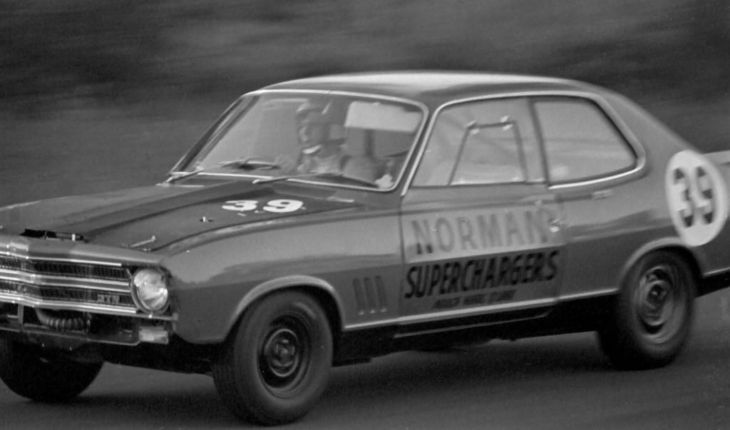 Bog stock standard 161ci (2600cc) straight-6 with a Norman 110 supercharger. Standard brakes, wheels, radials, suspension, exhaust, head and cam. Home made aluminium bonnet and door skins, interior gutted. The supercharger never reached it's full potential as the relief valve spring lifted constantly (too light). The photo was taken at the Warwick Farm (Sydney) esses during a Sports Sedans practice on the 2nd of May 1970. Bill can be seen thrashing the Torrie at the same meeting in the last few seconds of the 8mm video clip below: http://www.youtube.c...h?v=jjgNQy6YIRk Warwick Farm is close to home for me. Dad used to race there on-and-off in the late 60's, early 70's, though pretty informally (he was more often at Castlereigh, crewing a V8 humpy  ). Dad was part of a group of 100 young mechanics who were selected based on their performance to take a look at the newly released LC GTR, including hot laps around Warwick Farm. Shame the only racing over there is by hay-burners now . As an aside, Im writing an Eldred Norman anecdote.... Ill add this material to it (watch this space ). It needs some revision yet, and verifying by Mike, Bill and Bron before I post it though. Cheers, Harv (deputy apprentice Norman supercharger fiddler). |
|
|
|
|
Logged
|
|
|
|
|
|
|
Harv
|
|
« Reply #185 on: July 02, 2014, 06:48:00 AM » |
0
|
Thanks Alex - appreciated.
Cheers,
Harv
|
|
|
|
|
Logged
|
|
|
|
|
Harv
|
|
« Reply #186 on: July 07, 2014, 12:25:54 PM » |
0
|
Ladies and Gents, This post is a bit of a tease. As you are aware, as part of the Norman Supercharger Guide, I have a number of Normans to pull apart and put back together. One of the Normans on loan is Gary's Type 65, which has featured in a number of earlier posts (normally in pieces :lol: ). The teaser photo below shows how far we have come along with the overhaul: 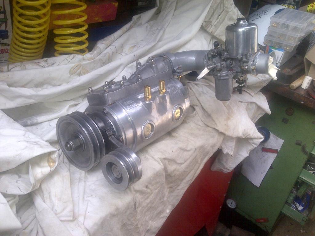 Cheers, Harv (deputy apprentice Norman supercharger fiddler). |
|
|
|
|
Logged
|
|
|
|
|
Harv
|
|
« Reply #187 on: July 07, 2014, 02:42:38 PM » |
0
|
Ladies and Gents, For this post, I will take a look at the drive system that we use on our Norman supercharger. As a starting point, I will focus on belts. For our Norman supercharged grey motor, we have a number of choices of drive system. For example, we could use: a) Direct drive off the crank snout. Direct drive has been used in a number of vehicles, including the Daimler-Benz race vehicles of the early 1900s and many GM Roots superchargers in diesel service. Your typical early Holden however has very little room at the front of the crank to direct mount a supercharger. Whilst not impossible, direct driving a Norman supercharger is not readily practicable, nor very period correct. b) A gear set. Gear driven superchargers are not that unusual, with Rolls Royce Merlin superchargers often being driven through single or two-speed gear drives. Gear drives are available from The Supercharger Store (see http://www.youtube.com/watch?feature=player_embedded&v=I0nizAm3bPw, which shows the ERA coupler fitted to one). Whilst not impossible, driving a Norman supercharger through gears is not readily practicable, nor very period correct. c) A chain drive, as used on Stud Beasleys Norman supercharged midget and Andrew Mustards supercharged Elfin (ses anecdote below). A chain drive is pictured below. 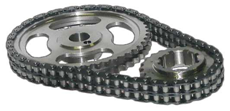 We could fit a single, double or even triple row chain to the supercharger, and drive them from toothed sprockets on both crank and supercharger snout. This would provide a very positive drive, with no slippage. However, there will also be absolutely no slip should the supercharger stall (for example if the fuel/air mixture inside the supercharger and inlet manifold ignites during a blower bang). This means that during blower bang events the jarring energy can be transferred via the belt to the crankshaft. This can be like the unstoppable force meeting the immovable object, and lead to bending of either the supercharger drive shaft or the engine crankshaft. Unless we are chasing every last ounce of horsepower from our Norman supercharger (and are willing to wear the risks of damage), this type of drive is not recommended. |
|
|
|
|
Logged
|
|
|
|
|
Harv
|
|
« Reply #188 on: July 07, 2014, 02:43:15 PM » |
0
|
d) A gilmer belt, as shown in the image below. 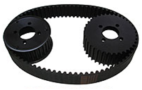 This is a toothed (positive drive) type of belt, again minimizing the risk of slippage. This type of drive is common on modern drag racing superchargers. Gilmer belts do pose similar risks to chains with respect to transmitting blower bangs. However, the Gilmer belt is more likely to shred/strip the belt teeth. Not such a big deal at the drag strip on a dedicated race car, though pretty frustrating in the Woolies carpark on a road-going car. Gilmer belts are also relatively wide compared to say a vee-belt. The real estate at the front of your typical Holden grey motor (between crank and radiator) is pretty small. Whilst not impossible, it can sometimes be a challenge to get a gilmer belt to fit. Gilmer belts are also relatively difficult to purchase
try finding one in your local SuperCheap. Again not really a problem if you carry a spare belt in the boot, but not too easy after stripping the belt in the middle of nowhere on a Sunday afternoon. Gilmer belts are period correct (and often seen) on the later (Mike) Norman superchargers, though not usually on the earlier (Eldred) Norman machines. e) A vee-belt. Vee-belts are period correct, and provide some ability for the belt to slip during a blower bang. They are relatively cheap, and readily available from SuperChepa, Repco etc. For these reasons it is recommended that vee-belts be used on most Norman supercharged applications. Vee-belts are typically available in two profiles normal/plain (see lower image below) and ribbed/notched (see upper image below). 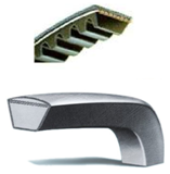 If a choice is available between normal and notched drive belts for Norman supercharger operation, then a normal belt should be chosen. The notched drive belt does have some benefits over the normal belt: They compress and grip better whilst still allowing good initial start-up slip (to avoid initially shocking the supercharger). The higher grip also allows them to compensate better for poor pulley surfaces. Less energy is required to bend the belt around the pulleys. They have a greater surface area for heat dissipation (i.e. they run cooler). However, because the notched belts grip better, they are less likely to slip during a blower bang. The normal type belts however provide enough slip to prevent this occurring. Note also that vee-belts are available in a ribbed format, as per the image below. 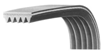 Ribbed belts are very common in modern vehicles. They began to be used in Holdens around the VL Commodore era, and have all but replaced normal vee-belts. Ribbed belts are easier to flex around tight pulleys. However, they are not very period correct for a Norman supercharger. |
|
|
|
|
Logged
|
|
|
|
|
Harv
|
|
« Reply #189 on: July 07, 2014, 02:45:06 PM » |
0
|
Given the above, I will focus on normal vee-belts in the discussion below. There are a vast number of systems for designing the sizes of vee-pulleys and the associated vee-belts. These range from simple automotive belts, through to agricultural belts to general purpose belts. One of the challenges of finding an appropriate belt drive for the Norman supercharger is that we will often have to match up automotive pulleys with other types in order to get the correct diameter, bore or number of grooves. The discussion below will try to pull together what is available, and some alternatives.
As a starting point, we will look at the original Holden vee-belts (and pulleys) found on grey motors. These are automotive type pulleys, and are likely to have been made to the SAE standard SAE J636 V-Belts and Pulleys. SAE J636 specifies both metric and imperial belts. Metric belts are labeled in three parts:
A number denoting the closest mm width of the belt (eg an 11 belt is roughly 11mm wide). This ranges from 6 to 23.
The letter A, denoting automotive
A number denoting the belt length (e.g. 990 for a belt that is 990mm long).
In the example above, the belt would be labeled 11A990, and the pulley referred to as an 11A.
Imperial belts and pulleys are labeled as decimals of the approximate pulley width. For example, a 0.250 pulley is 0.248 wide.
Most automotive aftermarket belts that are readily available in Australia (Bosch, Dayco) are metric automotive. Note that Holden grey motors use two different types of pulleys a wide belt on the earlier Holdens (FX and FJ), and a narrow belt on the later (FE through EJ) grey motors. For FX and FJ Holdens, a type 15A belt is used, whilst the later FE through EJ Holden grey motors utilize the narrower 11A belts. For example for FX/FJ Holdens Bosch recommend a 15A1130 belt, whilst for later grey motors a 11A0955 belt whilst Dayco specify a 15A11300 and either a 11A0900 or 11A0950 respectively. Whilst your typical early Holden is running a metric belt, it is very likely that the original Holden pulleys were specified imperial (Australia didnt start going metric until 1968, well into the red motor run, with industry making significant change in 1974, halfway to the blue motor in 1980). This means that the FX/FJ Holden wide pulleys (both water pump, alternator and crank) are likely to be 11/16 (0.600) pulleys, whilst the narrower FE-EJ pulleys are likely to be 0.440 pulleys.
In short, our early Holden is running an imperial automotive vee-pulley, and probably a metric automotive belt. To keep things simple, it would be nice to be able to walk into Repco or Supercheap and use a similar metric automotive belt (or belts) on our Norman supercharger. Not only is it easy to find a Repco or Supercheap, but they are also likely to have a wide variety of belt lengths. This will make it easier to fine tune the belt length (rather than say ordering in a specialty belt from an industrial supplier, only to find it is slightly too long or short).
|
|
|
|
|
Logged
|
|
|
|
|
Harv
|
|
« Reply #190 on: July 07, 2014, 02:45:44 PM » |
0
|
The question then becomes how many vee-belts we would need to drive our supercharger. From Supercharge!: Now as to how many belts are required to drive a particular supercharger. This depends on the type of supercharger, its size and the amount of boost intended. As a rough guide a standard car engine of 1500 c.c. using a seven pound supercharge and pulleys no smaller than 4 inches will require one 'A' section belt. A two litre with the same boost can manage with one 'B' section. A three litre will need two 'A' section. And a five litre V8 will need three 'B' section. Translating this to a 138ci (2260cc) grey motor, running 5-10psi of boost would infer a single B belt, or two A belts under heavy loading. This is very similar to the modeling I will present later, which shows that a single modern 11A belt will probably handle most Normans, whilst a second belt is appropriate under heavy use. Now that we have a view on belts, it is time to focus on the associated pulleys. For our Norman supercharger, we will be trying to connect the crank to the supercharger snout. This will involve a pulley on both shafts. It is possible to align the supercharger to the existing grey motor crank/water pump/generator pulley line, and use one belt to drive each of the fan, water pump, generator and Norman supercharger. However, for reasons which will be explored below this type of lienup is unusual and not recommended. Typically a dedicated supercharger belt will be required, and we will need to source both a supercharger drive pulley for the crank and a supercharger driven pulley for the supercharger snout. Bear in mind that we would ideally like to utilise the common (and cheap) 11A metric automotive belt profile. For the supercharger drive pulley, a neat alternative is to bolt a flat pulley to the front of the grey motor harmonic balancer. The original GMH grey motor harmonic balancers have a flat face, though only the central hole (which is tapped to 11/8 UNF to accept the harmonic balancer puller tool). However, aftermarket grey motor harmonic balancers are available from PowerBond, and supplied by Rare Spares. These are Rare Spares part number 7401305 for the wide-belt FX/FJ (PowerBond part number HB17B-N) and 7408676 for the narrow-belt FE-EJ style (HB1049-N). Anecdotally (and just in case any of the red motor guys are reading this ), the respective EH-HZ red motor part numbers are M40284 and HB17A-N. Each of these aftermarket harmonic balancers has three concentric bolt holes, as shown in the images below. 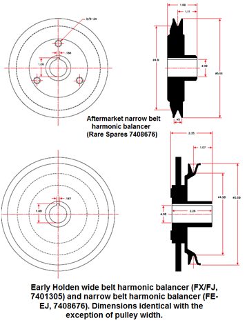 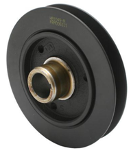 |
|
|
|
|
Logged
|
|
|
|
|
Harv
|
|
« Reply #191 on: July 07, 2014, 02:46:19 PM » |
0
|
The holes are tapped through the hub to 3/8-24UNF on a 213/16 (71.44mm) PCD. Whilst the holes are ostensibly there to mount a modern harmonic balancer puller tool, they also make a very neat mounting point to bolt up a flat pulley. The bolt-up pulleys from Holden red motors and Commodore Starfire 4-cylinder engines have this PCD, and are a neat bolt-on fit. An alternative is to find a flat pulley from another vehicle, drill three holes to the PCD above and bolt them on. Note that if you are sourcing pulleys (either drive or driven) from a wreck, almost all early Holdens (FE-WB, LC-UC Torana, VC-VK Commodore, VN-VS 308s) used the 11A metric/0.440 imperial pulleys. Be wary though that many of these models had the larger 13A metric/0.500 imperial pulleys on air conditioning. From VL Commodore onwards the six cylinder engines began to move towards the ribbed vee-belts. Additionally, care needs to be taken to ensure that the pulley is truly centered before marking out and drilling the holes. This is particularly important if the pulley chosen does not have the same centre bore as the grey motor crankshaft (~1). For example, small block Chev (SBC) double-row flat alloy pulleys are readily available. However, the SBC crank diameter is ~1¼. This means that there is a risk that a SBC pulley will not be centred, imparting vibration to the crankshaft (they grey motor needs no help in this department). The holes could be drilled oversized (sloppy on the bolts), tentatively fitted up and then the crank spun around. By watching the pulley spin, the out-of-centre can be seen. Some gentle taps with a hammer can get the alignment closer to centralized before tightening the bolts. All up, not the best process for removing crank vibration. An alternative is to use a concentric ring (like a thin washer) between the oversized (eg SBC) pulley bore and the grey motor crankshaft. Finding the exact correct size ring (or turning one up on a lathe) is equally not that easy. For the supercharger driven pulley, it is not too likely that a pulley will be sourced from another vehicle at the wreckers, and will instead need to be sourced from the aftermarket. Aftermarket pulleys are often sourced from industrial, rather than automotive suppliers. This means we will probably be mix-and-matching an automotive drive pulley with an industrial driven pulley. Aftermarket industrial pulley profiles are often referred to in articles about Norman superchargers (for example in Supercharge! Eldred refers to his HR Holden Type 110 supercharger being driven two A section belts, and his Australian Grand Prix Triumph TR2 G.M. 271 supercharger being driven by four). A common specification for industrial (often referred to as classical) pulleys is ISO 4183:1995 Belt drives -- Classical and narrow V-belts - Grooved pulleys (system based on datum width). This aligns well with the standards used by the Mechanical Power Transmission Association (MPTA), a North American association which drives vee-belt standardization. Classical pulleys are labeled by a letter (A, B, C, D) in increasing order of width. Note that there are standard classical pulleys, and deep groove pulleys, which have different dimensions. The table below shows the various automotive and classical pulley dimensions: 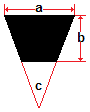 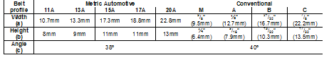 |
|
|
|
|
Logged
|
|
|
|
|
Harv
|
|
« Reply #192 on: July 07, 2014, 02:47:58 PM » |
0
|
The table below shows the dimensions for the various automotive and classical pulley sizes of the same rough size as an early Holden in order of pulley (and hence belt) width (perhaps a little easier to use than the table above): 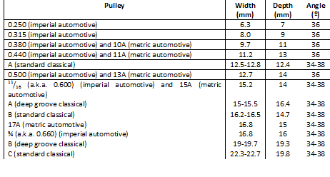 From the table, we can see that if we want to mix and match automotive and classical pulleys: an A standard classical pulley will be closest to the original 0.440 narrow grey motor pulleys used on FE-EJ Holdens, whilst an A deep-groove classical pulley will be closest to the 0.600 wide grey motor pulleys used on the earlier FX/FJ Holdens. Given that we would ideally like to utilise the common (and cheap) 11A metric automotive belt profile, this means we are hunting for an A classical pulley. Aftermarket die-cast aluminum pulleys are available from Stenco, an Australian manufacturer based in NSW: http://www.stenco.com.au/images/STENCO-Brochure.pdf. Stenco make both tapered bore and straight bore pulleys. The Norman supercharger shafts are straight bore, with the bore diameter around the varying between .868-1 and with a variety of keyways. When using Stenco pulleys it is likely that the pulley bore (and potentially also the keyway) will need to be bored/recut to suit the Norman supercharger. As an example, the pulley on Garys Type 65 Norman is a Stenco 5 2A unit. The 2A reflects a double pulley and A-profile. I suspect that this is a part number 2A0503 whose 1 bore and 3/16 keyway were machined back to 0.890 and ¼ respectively. Note that Stenco are quite capable of producing one-off pulleys to given bore/keyway dimensions. Be wary however in measuring a Norman supercharger in that they are a delightful mixture of imperial and metric sizes as an example, the Type 45 supercharger pulley has a 30mm bore and a 3/16 keyway. Note that for those wishing to drag race their Norman blown vehicles under the Australian National Drag Racing Association (ANDRA) rules, the ANDRA Rulebook General Regulations indicate that cast supercharger pulleys are prohibited in ALL classes. This would negate the ability to use STENCO pulleys. The Regulations also indicate that all vehicles equipped with belt driven superchargers must be fitted with a guard to prevent fuel line damage in the event of belt loss, except in cases where braided lines are used. As an aside, the typical Confederation of Australian Motor Sport (CAMS) grey motor road racing classes (Na for Touring Cars pre-1958 and Nb for Production Touring Cars per-1965) do not allow supercharging as it was not an original GMH option
vehicle wishing to compete in CAMS events with a Norman blown grey would need to compete in Regularity events where there are not supercharger prescriptions. |
|
|
|
|
Logged
|
|
|
|
|
Harv
|
|
« Reply #193 on: July 07, 2014, 02:48:29 PM » |
0
|
In order to drive the belt, the vee-pulley must have sufficient friction with the drive belt. Vee-belts do not actually bottom-out in the grooves, but instead transmit their driving force through the side walls of the vee groove. As load increases, the belts smoosh further into the groove, increasing the contact area and hence grip. The amount of grip that we can generate with a vee-belt is proportional to the square root of the belt/pulley contact area doubling the contact area gives 40% more grip. There are two number of ways we can increase contact area: a) By using larger pulleys. The relative sizes of the pulleys (drive and driven) is largely determined by amount of boost required, which we have calculated below. In practical terms for our Norman supercharged grey motor, it is likely that there will be limitations on the availability of the crank pulley. This will probably then lead to using whatever crank pulley is available, then tuning the supercharger driven pulley. If we have a choice, we should aim for larger pulleys. As well as increasing contact area, the larger pulley diameters tend to flex the belt through less of an angle. This dramatically reduces belt loading and increases belt life. As a rough guide (and as noted in Supercharge!), we should be aiming for pulleys no smaller than 4 in diameter. As a comparison, the standard grey motor harmonic balancer has a 45/8 diameter, an approximately 1 bore and a 3/16 keyway. b) By increasing belt wrap. Belt wrap is the amount (or angle) that the belt is in contact with the supercharger pulleys, measured through the pulley centerline see image below. 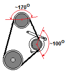 The higher the belt wrap, the more contact area and better grip. Often we have little choice about where the crankshaft and supercharger pulleys are relative to each other manifolding becomes the constraint. This means there is not much room to move the supercharger around to increase belt wrap. However, we can sometimes use an idler or tensioner pulley to increase belt wrap, as we will see below. |
|
|
|
|
Logged
|
|
|
|
|
Harv
|
|
« Reply #194 on: July 07, 2014, 02:49:05 PM » |
0
|
Whilst steel is far stronger than aluminum for supercharger pulleys, we are often likely to be limited to what is available in the market place. Chromed-steel pulleys should be avoided where possible due to the very slippery chrome surface promoting belt slip. Where aluminum pulleys are used, consideration should be made to having the groove faces hard anodized to reduce wear. Plastic is generally not suitable for supercharger pulleys, though is sometimes used for idler pulleys, and will be discussed below. Having sorted out our belt and pulley, we can now look at tensioning it. As the supercharger drive belt is loaded, there is a strong tendency for the belt to move into a more circular shape. This phenomena is called orbiting, and can be seen by the green belt shown in the image below.  Orbiting reduces belt wrap, which in turn reduces the grip that the belt has on the pulley, leading to slippage. To reduce orbiting we can put the belt under tension in a number of ways. In the standard Holden grey motor lineup, the engine belt is crank driven, and drives both the engine fan/water pump, and the generator. This lineup is shown in the image below. 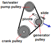 Whilst the crank pulley and fan/water pump pulley are fixed to the engine, the generator is able to pivot about two points. By moving the generator in the direction of the blue arrow, additional tension is placed on the belt. The factory specification for belt tensioning indicates there should be 3/8 of slack between the fan/water pump pulley and the generator pulley. I will refer to this type of drive system (where one of the driven pulleys and attached equipment swings) as swinging in the text below. |
|
|
|
|
Logged
|
|
|
|
|
Harv
|
|
« Reply #195 on: July 07, 2014, 02:49:47 PM » |
0
|
A similar swinging drive system can be used to provide tension to the supercharger belt. If the same drive belt is used to drive each of the engine fan/water pump, the generator and the supercharger then the tension can be applied by swinging the generator. A swinging system of this type is shown in the image below. 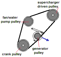 This type of system however tends to have very low belt wrap, significantly increasing the amount of tension required to achieve a non-slip drive. Additionally, the belt is now driving a fan, a water pump, a generator and a supercharger. This is a significant amount of load for one belt to carry. For these reasons, this type of drive system is not recommended. A different swinging drive system can be achieved if a dedicated supercharger drive belt is utilized. In this case the tension can be applied by swinging the supercharger. This type of drive system can achieve good belt wrap, lowering the amount of tension required to achieve a non-slip drive. Given the belt is dedicated to driving the supercharger, the loading is lessened (and either fewer belts can be used, the belt profile reduced or the belt life extended). However, swinging the supercharger is not without its down sides. The carburetor must also swing with the supercharger, which can provide some unique float bowl angles and hence additional work to attain a satisfactory fuel level. Further, the manifolding between the supercharger and the engines cylinder head must have sufficient flexibility to allow the supercharger to move. This can be achieved by the use of pipe, either rubber/silicon or convoluted metal. A drive system of this type is shown in the figure below, and also in the photograph below of the supercharger removed from the Bobcat custom humpy, and subsequently fitted to Anthony Harradines EJ Holden Premier. 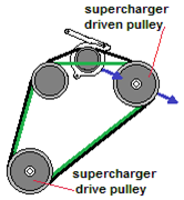 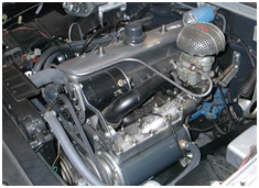 Anthonys system has a triple-groove pulley fitted to each of the crank, fan/water pump and supercharger. Two of the three grooves on these items are belted together, giving the green drive line shown in the image above. The third pulley groove on each of the crank, fan/water pump and supercharger is also run to the generator, which has a single-groove pulley. Both the generator and supercharger can be independently pivoted, providing belt tension as per the blue arrows above. |
|
|
|
|
Logged
|
|
|
|
|
Harv
|
|
« Reply #196 on: July 07, 2014, 02:52:43 PM » |
0
|
An alternative to a swinging drive system is to apply an idler (also known as a jockey or tensioner) pulley to the system. In this case the driven pulleys are all fixed, and the idler pulley moves to provide belt tension to the supercharger. The idler drive system shown below has a dedicated supercharger drive belt(s), shown in green. The idler pulley is placed inboard of the belt. 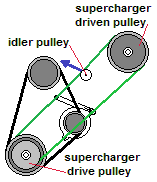 By moving the idler pulley in the direction of the blue arrow, additional tension is placed on the belt. In this case the idler pulley runs on the vee-side of the belt, and must have a vee-pulley face. Systems of this type reduce belt wrap, increasing the amount of tension required to achieve a non-slip drive. The drive system on Garys Type 65, shown in the image below, has an inboard idler drive system. 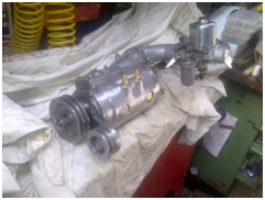 The idler drive system shown below again has a dedicated supercharger drive belt(s), though in this case the idler is placed outboard of the belt. 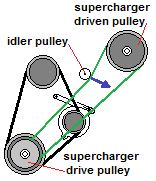 |
|
|
|
|
Logged
|
|
|
|
|
Harv
|
|
« Reply #197 on: July 07, 2014, 03:21:37 PM » |
0
|
By moving the idler pulley in the direction of the blue arrow, additional tension is placed on the belt. In this case the idler pulley runs on the back of the belt, and must have a smooth pulley face. Systems of this type increase belt wrap, lowering the amount of tension required to achieve a non-slip drive. This system is preferable to the one shown above. Note however that in this case the belt is being flexed additionally compared to the system above, which can reduce belt life. The Norman superchargers shown in the images below utilize this type of drive system.
|
|
|
|
|
Logged
|
|
|
|
|
Harv
|
|
« Reply #198 on: July 07, 2014, 03:23:03 PM » |
0
|
... can't seem to post the images for some reason  . Whilst the supercharger and crank pulley locations are often relatively fixed, there is generally more leeway to move around the idler pulley location. To mount an idler pulley, a number of options are available. These include: a) Using a lever-type bracket directly back to the engine block (similar to the photograph of Cliff Kiss FED above, b) Marking an engine plate-type bracket and mounting the idler spindle in a slot, similar to the image below, 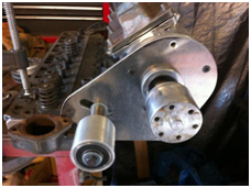 c) Making a clamp-type bracket that clamps around the supercharger snout. This type of mounting is very typical of Norman superchargers, and can be seen in several of the images above. The image below shows the typical dimensions for a Type 65 clamp-type idler. 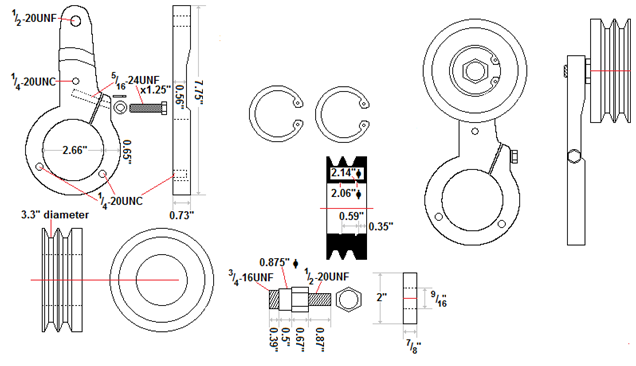 |
|
|
|
|
Logged
|
|
|
|
|
Harv
|
|
« Reply #199 on: July 07, 2014, 03:24:50 PM » |
0
|
In terms of location, note that supercharger drive belts have a slack side and a drive side. Like a piece of rope, the crank can pull on a belt but cannot push on it. With the crank rotation as per the blue arrows in the image below, the slack side is on the drivers side of the vehicle, and the drive side of the belt on the passengers side. 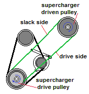 Where a choice is available, the idler should be installed on the slack side of the belt. This reduces loading on both the belt and the idler. The idler pulley should be located at least twice the idler pulley diameter away from the nearest other pulley. This gives the belt a chance to relax after its last bending, get aligned if the pulleys are not dead-true and also to pass through some air and cool down, each of which will extend belt life. Regardless of whether a swinging or idler system is used is, the belts are under considerable duress during service. Stops, starts, acceleration and deceleration, the odd blower bang and constant vibration all add up to gradually slacken the belt tensioning. There is a trick that can both assist in maintaining tension, and also in getting the right tension in the first place. This is to utilize a turnbuckle (or similar threaded connector) to push against the idler pulley. |
|
|
|
|
Logged
|
|
|
|
|


