|
Harv
|
 |
« Reply #340 on: January 24, 2016, 10:02:31 AM » |
0
|
Some learnings from the thesis:
The Norman supercharger has an adiabatic efficiency of 45-60% for 2-10psi boost. This lines up pretty well with the numbers I have used earlier in this post when we modelled the Norman. I had assumed 60%, whilst other resources indicate 70% (Eldred) and 50-65% (Corky Bell).
At 4000rpm (typical operating range for a wide-open early Holden Norman), the volumetric efficiency starts at around 80% at 2psi boost, and drops to 70% at 10psi. Increasing pressure ratio lowers the efficiency due to the increased internal pressure recirculating gas within the supercharger. This is a little lower than the values I used in the modelling I assumed 90%, compared to literature values of 82-90% (William Lyons), 90% (Royce Brown) and 85% (C.F. Taylor).
The 200 Norman casing was measured (using the modern method, not Eldred's method) to give 115ci/rev (very similar to the Type 65). The 16% internal compression ratio of a standard Norman was close to optimal (i.e. increasing or decreasing internal compression was not beneficial).
Four vane materialss were tested: Bakelite, Feroform F31 (similar to the Feroform F57 I have discussed earlier), Tuffclad Moly (a self-lubricating thermoplastic) and Nylacast Moly (a self lubricating thermoplastic filled with nylon). Of note:
a) vane wear for the Bakelite was very similar to that noted by Mike Norman about 4-5mm per 20,000km of driving. One of the reasons for this is that Mikes design has a very high vane tip speed due to its large casing diameter some 49m/s at 6000rpm, which is nearly four times faster than a grey motor piston at redline.
b) using water alone as a lubricant for Bakelite vanes lead to liner scoring. Oil is required.
c) water can be used as a lubricant for the Feroform and Tuffclad Moly materials. It removes frictional heat far better than oil, probably by partial vapourisation.
c) friction power loss was not noticeably different for the different vane materials. However, the Nylacast Moly vanes tended to pick-up in the vane slots (even with water lubrication) and hence are not suitable.
d) Both the Nylacast Moly and Tuffcast Moly were more susceptible to delamination or cracking than Bakelite. The slots cut out for the vane spring carriers act as a stress riser.
|
|
|
|
|
 Logged
|
|
|
|
|
Harv
|
|
« Reply #341 on: January 24, 2016, 10:03:55 AM » |
0
|
Vane rattle was examined, and found to be due to: a) too much clearance between the vane and slot. This stops once operating temperature is reached. Note that a clearance of 0.005 was recommended for Bakelite vanes (this is perhaps a little more accurate than Eldreds flop fit specification), and is a useful number for anyone milling down their own replacement vanes. b) low speeds (<1500rpm) where the small centrifugal forces are unable to overcome slot friction and the weight of the vanes. This is where the vane springs are useful. Of note, there was no discernible power loss from using the vane springs (i.e. they do not increase friction, as the centrifugal forces on the vanes far exceed the spring tension). Whilst four-vane rotors are more efficient and do not increase shaft power, they are not a simple swap-in for the exiting Normans. Four-vane rotors were tried, but delaminated over 2000 pm as the vane stroke was too high in the existing casing. A word to the wise if replacing the rotor in one of Mikes Normans, do not be tempted to use a 4-vane design unless the end-plates are remanufactured to give less vane stroke. The seal between the end-plate and casing was effected through the use of a synthetic sealing strip (I have yet to find one of these in a Norman
they tend to get discarded, and replaced with a line of sealant like Sikaflex Just like Roots superchargers, the positive displacement Norman delivers a pulsing flow at the discharge ports. Four-vane rotors delivered smoother flow than three-vane rotors. The attached graph shows how the discharge pressure changes over time. Note that a Norman running at a nominal boost pressure of 10psi has the discharge port oscillating between 7 and 11 psi (albeit over a very short time frame). 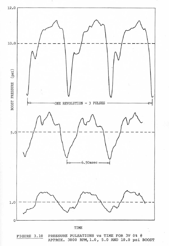 The nature and surface finish of all sliding surfaces have to be very hard and smooth to reduce friction and vane wear. A surface finish of <16µinch is recommended, as per the red line in the chart below. As a comparison, a rough turned item with visible toolmarks is about 500µinch, a smooth machined surface around 125µinch, bearing surfaces are around 32µinch, and fine lapped surfaces are around 1µinch. 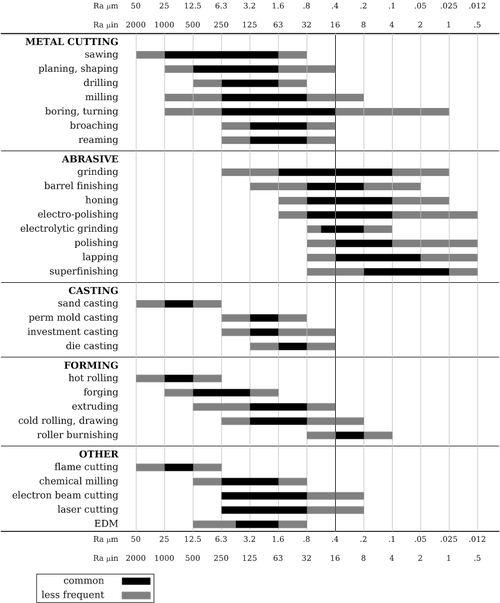 The document also contains a compressor map for the 200 Norman this is the only Norman compressor map that I am aware of: 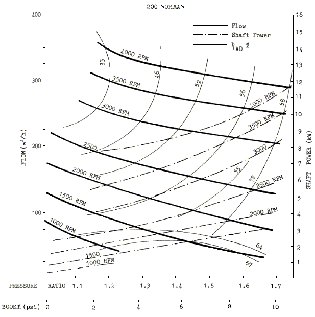 Cheers, Harv (deputy apprentice Norman supercharger fiddler). |
|
|
|
|
Logged
|
|
|
|
|
Harv
|
|
« Reply #342 on: February 15, 2016, 12:09:18 PM » |
0
|
Ladies and Gents, A quick post to share with you an article from Chopped No. 7. The article features Grantleys Norman-blown humpy. Thanks to Kyle for providing approval to publish the copyrighted article here. 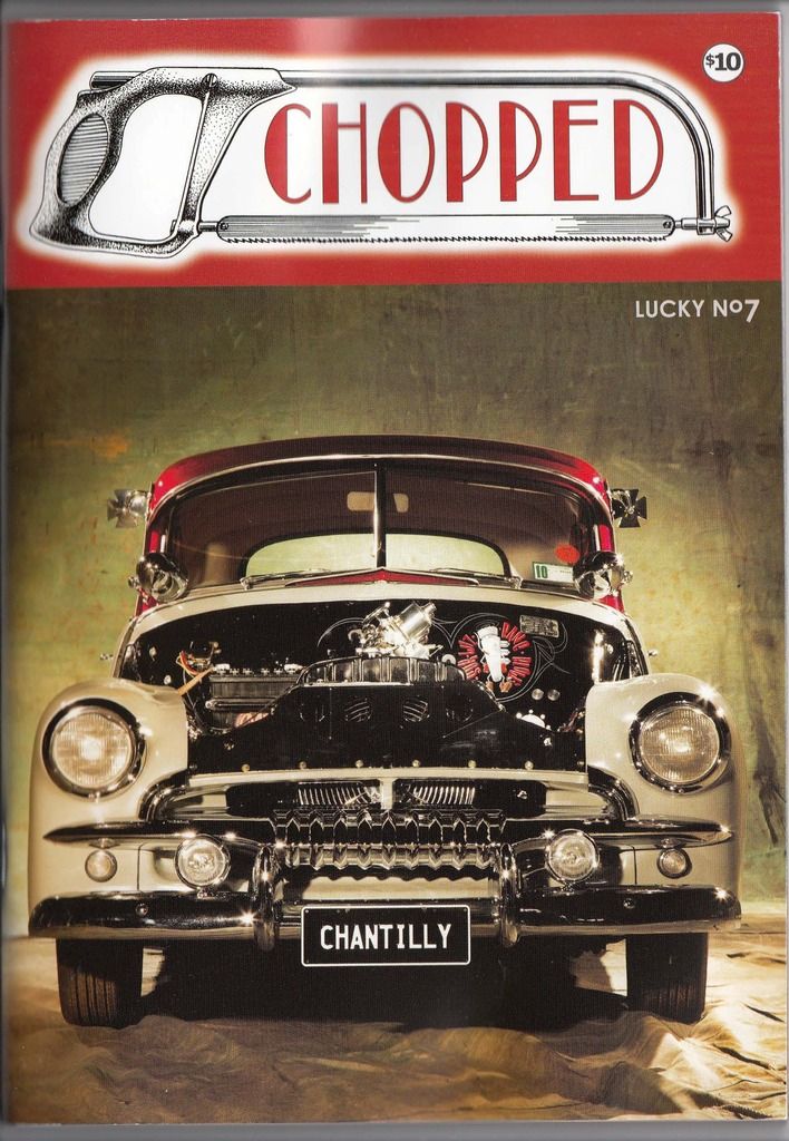 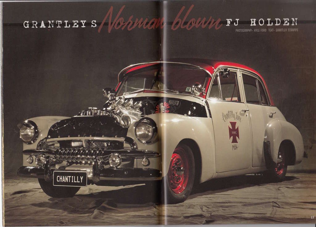 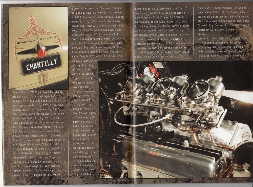 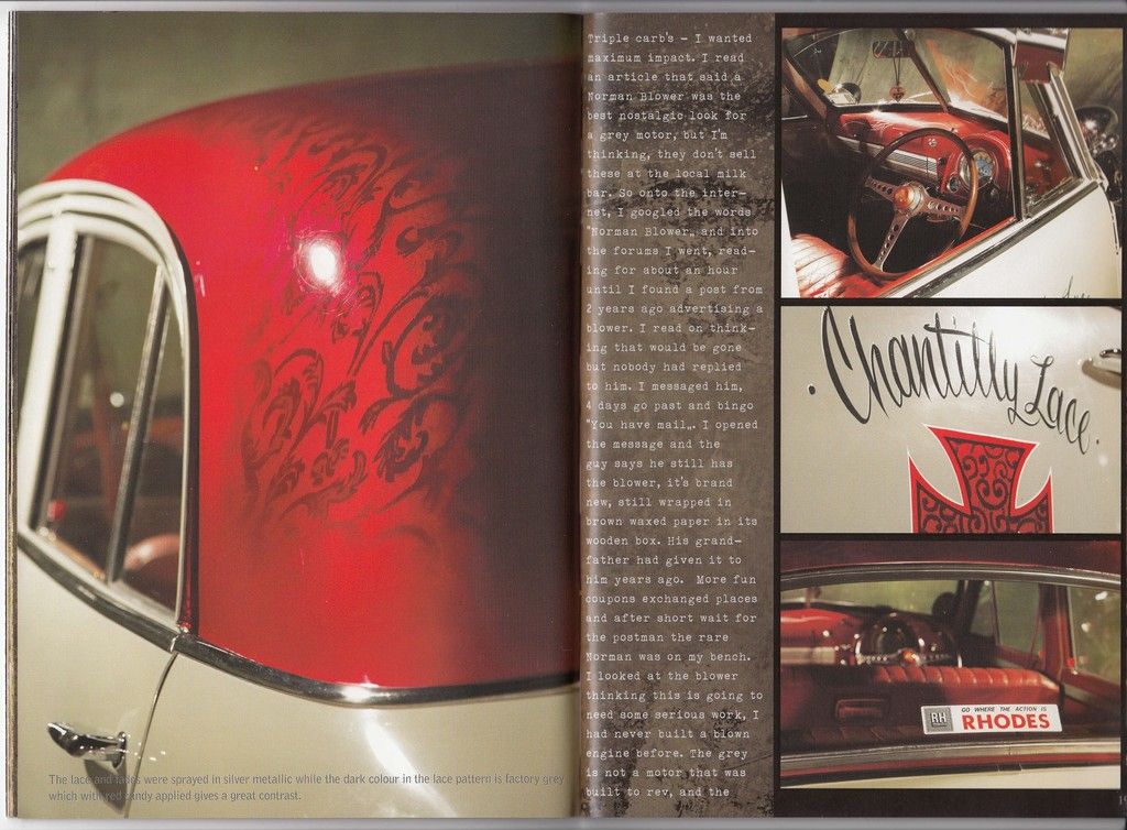 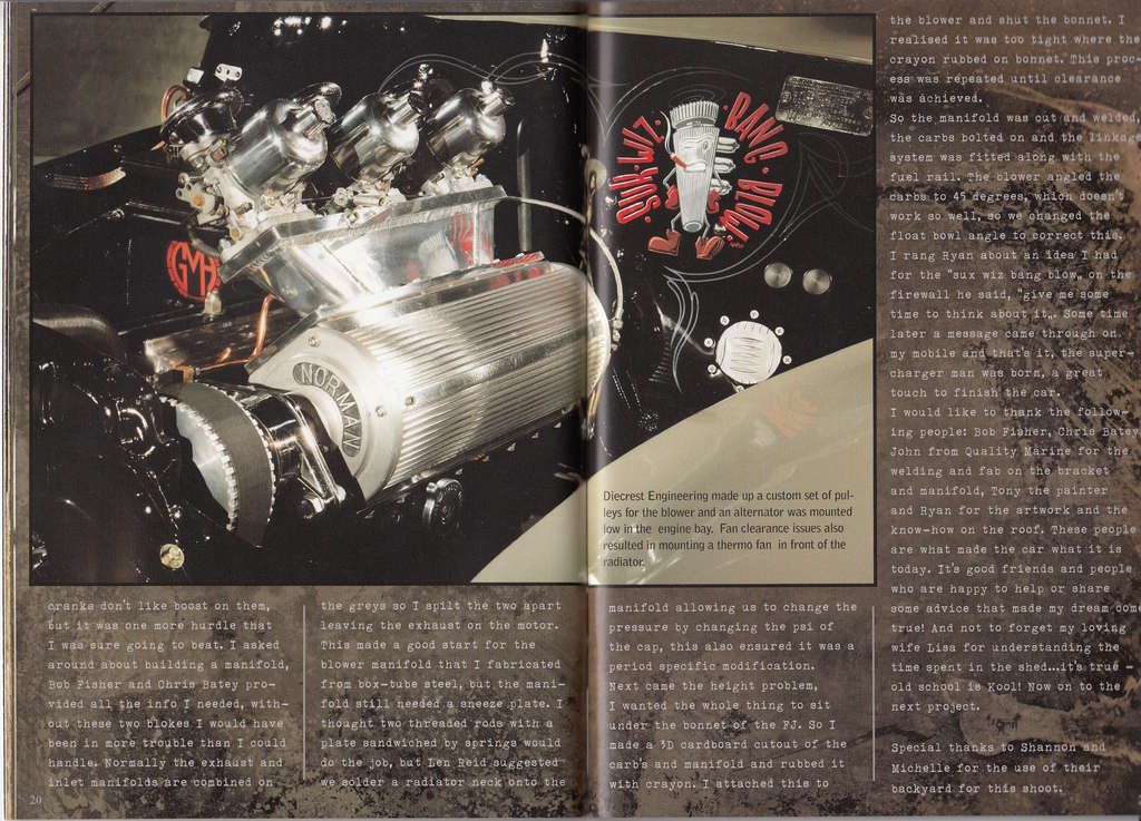 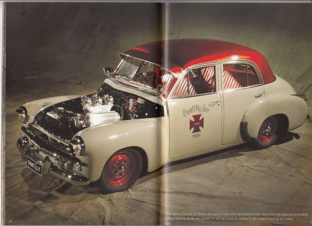 Cheers, Harv |
|
|
|
|
Logged
|
|
|
|
|
Harv
|
|
« Reply #343 on: April 05, 2016, 01:40:55 PM » |
0
|
Ladies and Gents, Attached below some more photos of Matt Browns Norman. From what I can see: It's a Type 65 Norman. It could either by a Lightweight (solid steel rotor) or Super Lightweight (steel rotor made hollow by welding steel plates together). Matt has weighed the machine, and it seems very light (10.7kg, whilst Gary Claypole's Lightweight weighs 20kg). I am itching to see the rotor in Matts machine
it could well be a Super Lightweight rotor, which I have not yet seen before in the flesh. Looks like a home-made carburettor-to-supercharger manifold, but a pretty good copy nonetheless. 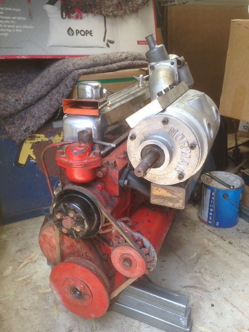 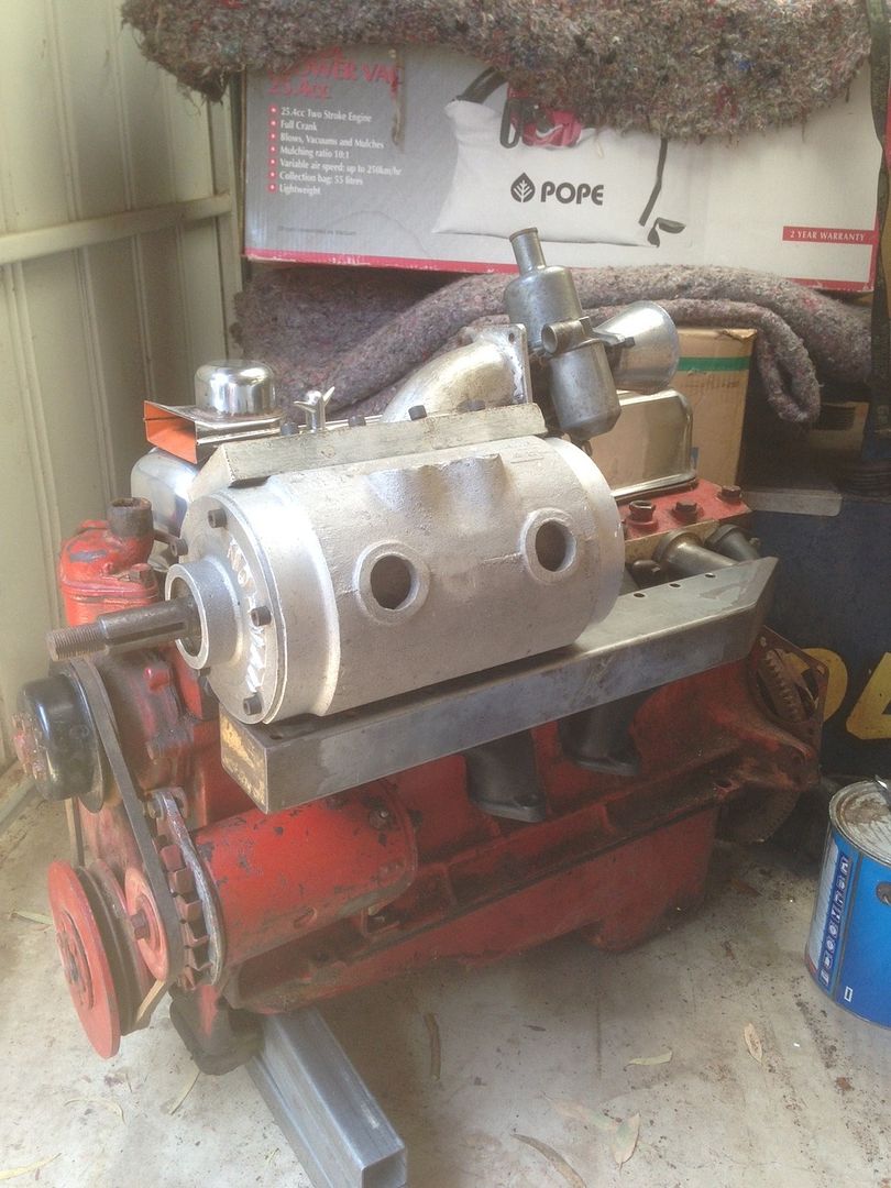 The casting number (22) is pretty meaningless. All the alloy cased Type 65's that I have seen (e.g. Paul's, Gary's) have that same casting number. 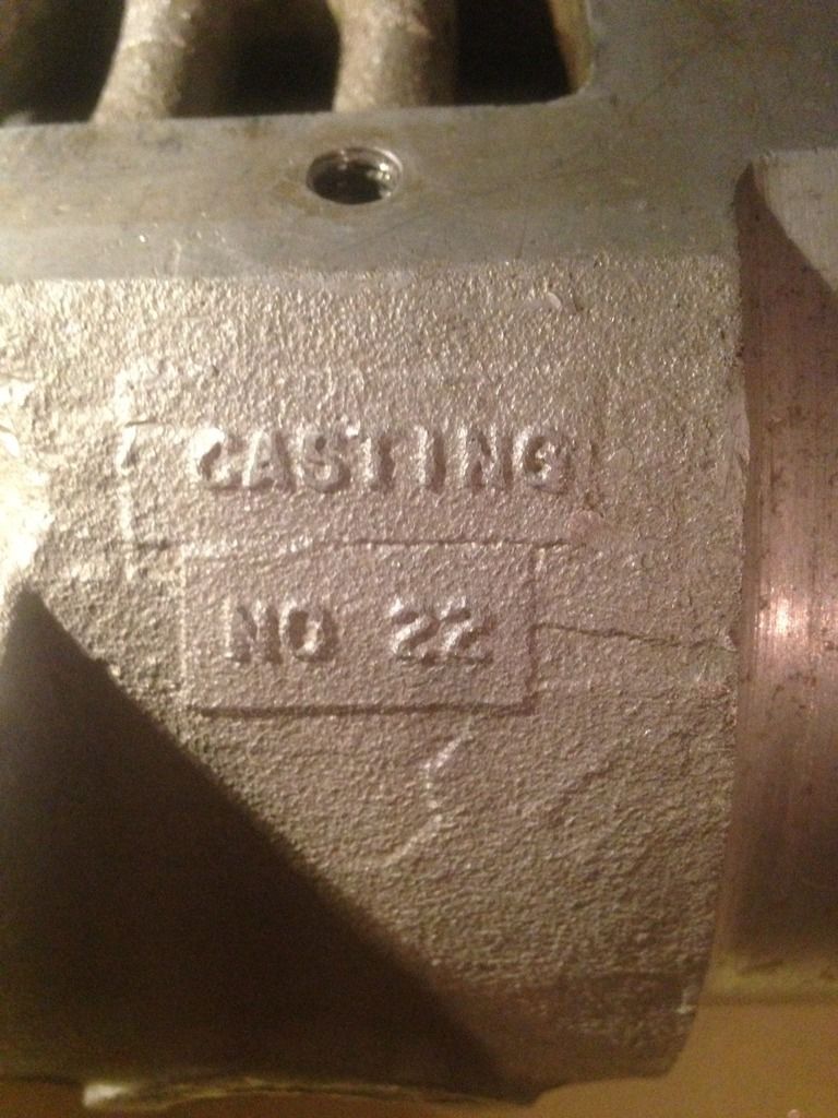 The drive-end plate stamping (516) is interesting, and more like a serial number. The numbers were not consistently applied by Eldred though (for example neither Paul nor Gary's has an end-plate stamping). This is the third one I've seen - Ian Barnard has 522, and Ted Robinette has 513, both on steel-cased Type 65s. 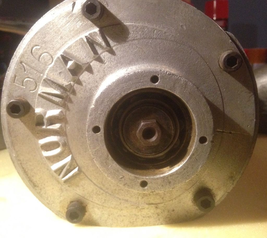 The non-drive end is interesting. Most Type 65's have a plain end-plate boss, into which is driven a welsh plug. Matts machine non-drive end end-plate has been drilled and tapped for four setscrews. I have seen this on other machines, including both my Type 45 and Type 75. I suspect that the four holes mean that Matts machine was once fitted up with a clutch (the same as my Type 75), which would make it a Deluxe. The four holes allow the clutch hydraulic driver unit to be bolted to the non-drive end of the Norman. The other clue is that the non-drive end of Matts driveshaft has a nut fitted, the same as my clutched Type 75. The non-clutched Normans (like Garys) have just a bare shaft sticking out through the bearing on the non-drive end. I've seen rotation directions stamped into Normans before, sometimes as plain arrows, sometimes as ROTATION, but this is the first one I've seen with MUST ROTATE stamped into it. 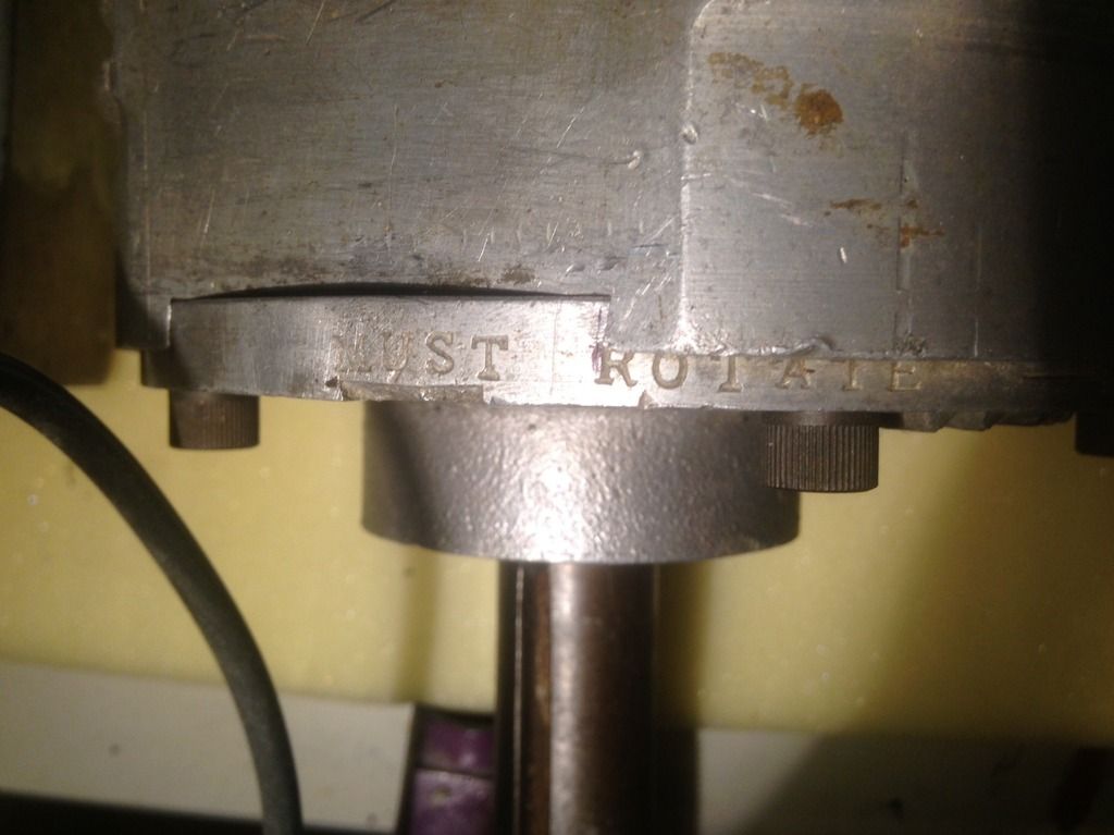 Matt has two supercharger-to-cylinder head manifolds. One looks to be made from steel, and mounts the supercharger up high (this is the one that is being used to mount the Norman to the red-painted grey motor in the photos above). This is period correct. The other manifold is used to mount the supercharger low, in the place that the generator normally sits. The slip-in flange is unusual, and probably robbed off an original carburettor-to-supercharger manifold - they normally have a hose connected where you have the flange. There are very few of these manifolds surviving - Anthony Harradine's supercharger (ex Bobcat) in his EJ Premier is one of few. 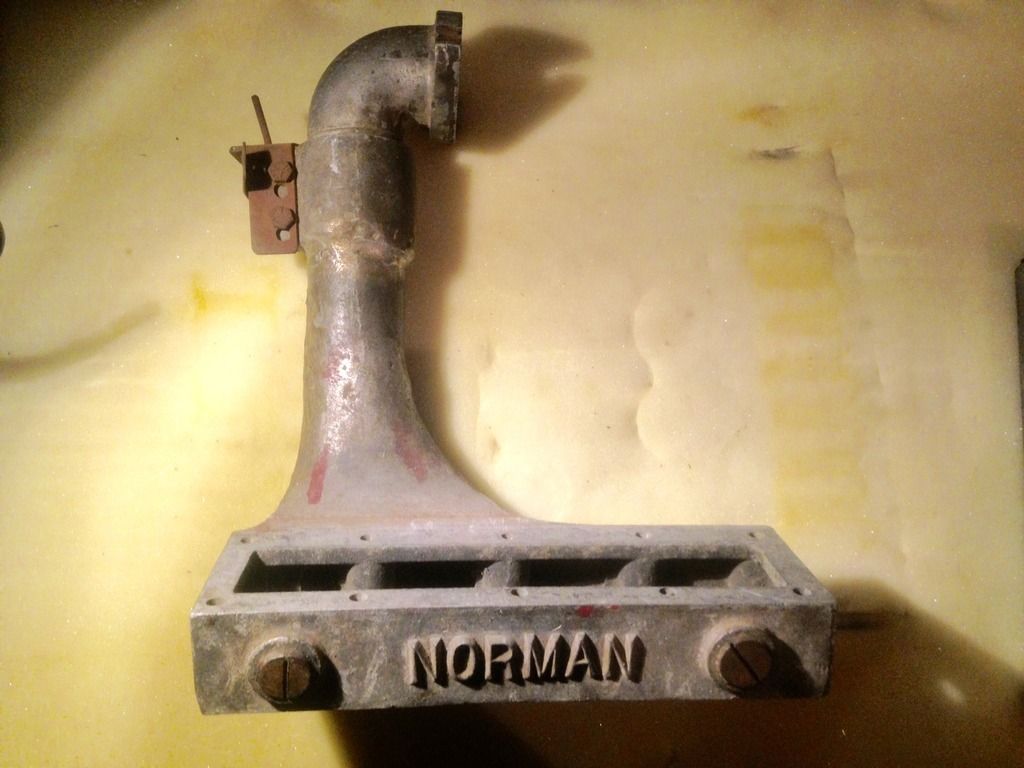 Cheers, Harv |
|
|
|
« Last Edit: April 18, 2016, 11:05:34 AM by RET »
|
Logged
|
|
|
|
|
Harv
|
|
« Reply #344 on: April 24, 2016, 09:57:20 AM » |
0
|
One project that is slowly percolating along is my meth monster Norman. I intend to Norman-supercharge my FB daily driver, and putt around running on SU carbs and petrol fuel. For the nostalgia drags (and maybe some Wednesday night WSID drags) I will change the intake to Hilborn injection, and the fuel to methanol. Ive got the supercharger and injection, and have been slowly piecing together the other bits (dry sump etc). Ive been slowly accumulating the bits for the fuel system: 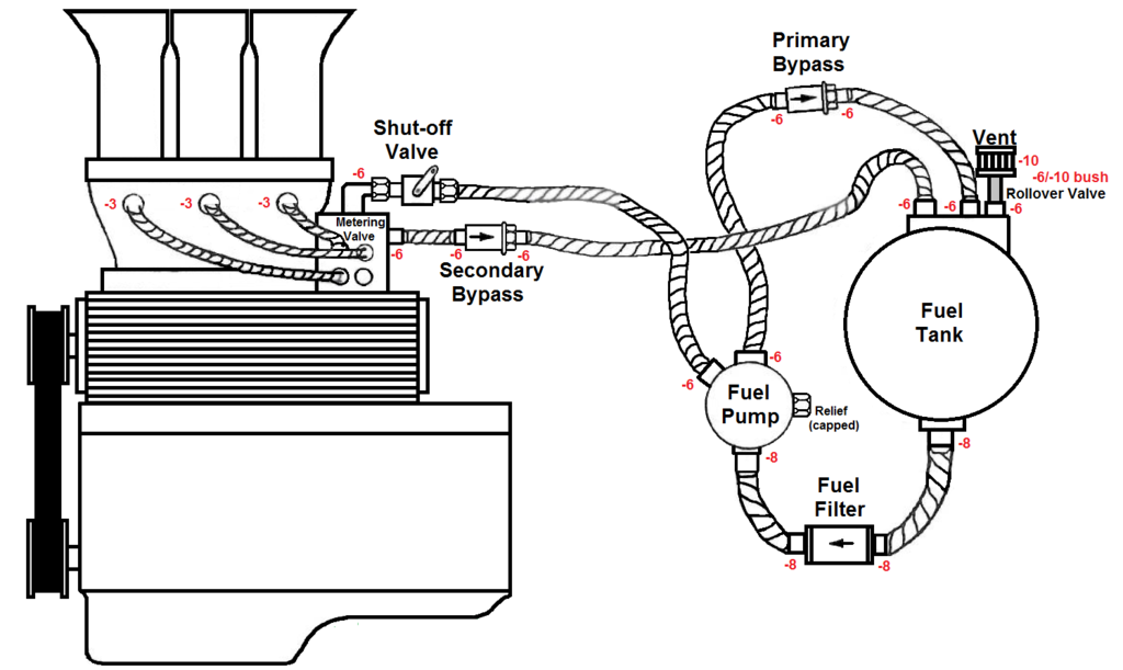 I wanted a Moon tank to fuel the alky into the meth monster. It took me a while, but I finally got all the bits together and got the fuel tank made up. The Moon tank will sit in front of the grille, and be able to be removed when the car is in daily-driver use. I looked at buying a genuine Moon tank, but they are around $550. They do not have enough fittings for fuel injection, so I would have to have some nipples TIG welded in. They are also not baffled (the fuel return would churn the tank up), so the Moon tank would also need to be cut open to put in a baffle. For that much money, and still needing work, I figured there had to be a better way. I took a brand-new 8.5kg gas bottle, which owes me about $30 from Bunnings. Assuming the tank is about 75% full, and that the meth-monster is punching out around 150BHP, the tank should last about 20 minutes on petrol, or 8 minutes on methanol. 8 minutes should be enough for queueing in the staging lanes, a run down the strip, and the return lane drive back to the pits. 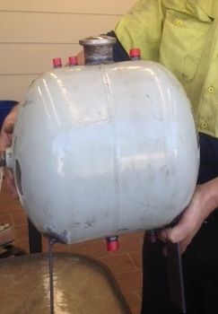 I cut the foot ring and valve collar off the bottle, and ground the welds flush. The inlet/outlet valve for the bottle unscrews. It is a tapered gas thread (¾-14NGT), and took a damn long extension bar to get enough torque to get if off. I dont need that particular hole, and sourced a plug to suit. Finding a NGT plug is near impossible, and I ended up having a good conversation with Gameco ( http://gameco.com.au/) who confirmed that ¾-14NPT is very similar to NGT, and close enough for what I intend to do with it. Probably wouldnt use a NPT plug for LPG service, but OK for this job. I then marked out and drilled holes for the fittings. The top of the tank has two returns (primary and secondary bypass), which have -6AN nipples (the equivalent of 3/8 pipe). I made a slit in the tank wall, and have inserted some steel plate 1 under the two return lines. This plate acts as a baffle/splash plate, preventing the returning fuel from stirring up (and aerating) the tank contents. This type of baffling is recommended by Kinsler for Moon tanks (see the diagram down the bottom of page 179: http://www.kinsler.com/Kinsler-Handbook/HTML/#178). The tank has another -6AN nipple for a tank breather. The breather gets a nice filter, and also a rollover valve (in case things go pear-shaped). The fuel tank outlet (under the tank) is plumbed with a -8AN nipple (½ pipe). A second -8AN nipple will let me fit a drain cock. I used an early Holden filler neck (many thanks Jim), which has an original Holden cap on it (should match the era of the FB nicely). The ANDRA rules require that the cap be positively locked. There is a small lug on the tank to anchor safety wire. I will drill a small hole in the cap to suit the safety wire, and solder the original cap vent hole shut. The two legs under the tank have been cut from steel plate. They are a little long for now, but can be trimmed later. I will make up some brackets to pick up the FB bumper bar irons (plan at this stage is to unbolt the bumper bar centre section and leave the two end sections in place). Still got to give the tank a rub back and some paint
not sure what colour yet but probably silver RustGuard. By using scrap, and my brother-in-laws welding skills, the tank owes me about $60 all up. By the time I refitted a Moon tank it would have cost $620. Not a bad saving. Cheers, Harv |
|
|
|
|
Logged
|
|
|
|
|
Harv
|
|
« Reply #345 on: May 31, 2016, 12:15:00 PM » |
0
|
Ladies and gents,
Having spoken to the seller, I thought Id post some more info on the Norman that is currently on eBay, along with some things that stood out for me.
The unit is a water cooled, cast iron cased Type 65. The unit was run in an FJ Holden hillclimb car in the early 90s. The unit had gone through several owners (mainly changing hands without being on a car) prior to purchase. The humpy was running a grey motor with a Vauxhall 12-port head and crank. The motor had been bored out significantly, and had a habit of blowing the copper head gaskets (between bores) when running in supercharged configuration.
The vehicle originally ran motorcycle carbs (probably Amals), though suffered from fuel surge. The carbs were replaced by the Norman, fed by the twin 2 SUs (thats a lotta carb for a Norman blown grey that is not running alky). The Norman was later replaced by triple SUs. The vehicle ran BP100, with water injection. Drive for the Norman was taken from a chain. This required a significant drive shaft extension, made to be a tapered (interference) fit to the original supercharger drive shaft. The driveshaft extension has been subsequently cut off. The Norman was run without water cooling (due to the short duration hill climbs it was used for), with the water inlet/outlets blocked by brass plugs.
The Norman has been rephrased at some stage notice that the end plate holes have been redrilled. The end plates are eccentric, so turning them in this manner moves the low point (where the rotor is closest to the casing). This can change both the Norman capacity and pressure output (depending on how much rotation is achieved, and in which direction). It would be interesting to see the internals of this machine to map out the exact change (hint hint
if someone purchases this machine, please give me a yell and Ill walk you through how to remeasure the Norman). Rephasing Normans is unusual, though is relatively common in Wray machines amongst the MGTC crowd (see my Wray anecdote for details of this).
The Norman is also unusual in that this is the first time I have seen the serial number (481) stamped on the casing and the carburettor-to-supercharger manifold. All other early Normans I have seen have been either unstamped, or stamped on the end plates only. Note that the non-drive end plates on this machine have not been drilled and tapped, signifying it has been a Standard (unclutched) model rather than a Deluxe (clutched).
|
|
|
|
|
Logged
|
|
|
|
|
Harv
|
|
« Reply #346 on: May 31, 2016, 12:16:17 PM » |
0
|
|
|
|
|
|
Logged
|
|
|
|
|
Harv
|
|
« Reply #347 on: June 05, 2016, 05:12:30 PM » |
0
|
Ladies and gents, I was working through my Norman notes, and came across some material that I dont think Ive posted before apologies in advance if I have. In my previous Wray supercharger anecdote, I mentioned that in the local (Australian) forced induction field there were numerous people bolting on (or making kits for) imported superchargers in the 50s and 60s. Whilst this is a little different to Norman and Wray (who were building superchargers from scratch), the kit builders were both contemporaries and competitors to the Norman supercharger. One such contemporary was Barry Ekins. Barry originally became interested in superchargers when he bought a Marshall-blown 1300cc MG/TA Special around 1959. The car, owned by Alan Tomlinson, had previously won the 1939 Australian Grand Prix in Lobethal, South Australia. Tomlinson, who won the AGP at age 22 and is shown in the event in the photo below, has described the circuit as bloody dangerous to drive on. 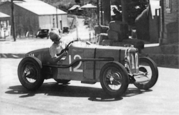 |
|
|
|
|
Logged
|
|
|
|
|
Harv
|
|
« Reply #348 on: June 05, 2016, 05:14:03 PM » |
0
|
Barry operated in the late 1960s in Sydney, utilising the Marshall-Nordec Roots-type supercharger.  Marshall is a large UK automotive and aircraft company, which started in the early 1900's and continues to operate today. I have confirmed that this Marshall neither manufactured superchargers, nor licensed the design (with thanks to Marshall, who were incredibly helpful). Sir George Godfrey and Partners made Marshall-Roots superchargers, both for aviation service and for automotive use. There are a number of advertisements advertising them doing so: http://www.aviationancestry.co.uk/?companies/&companyName=Sir+George+Godfrey+%26+PartnersGodfrey traded from at least the 1930s, until being taken over by Howden Wade Ltd (who were once Wade Engineering, and now trade as Hadron SR) in 1955. I have been unable to trace back the origins of the Marshall component of the Marshall-Rootes name for these type of superchargers, despite much hunting. Godfrey supplied the Marshall-Godfrey superchargers for the World War 2 effort, where they were used as high-altitude aircraft cabin blowers and for snorkel blowing on submarines. Following the war, a significant number of these machines were surplus. L.M. Ballamy was able to secure the rights to use these surplus machines for automotive supercharging. Ballamy did not manufacture the superchargers, rather they kitted them into post-war vehicles including Ford 8s and 10s, Vauxhall 10s and 12s, MG TCs and even at least one E93a Ford Prefect. Ballamys company, L.M. Ballamy, Consulting and Experimental Engineers began in the UK in 1939. In 1946 the business was reorganised as North Downs Engineering Co (Nordec). The company continued supplying supercharging kits (based on the Marshall supercharger) as well as retaining the rights to some of Ballamys patents. In 1947 some of Nordecs engineers, designers and managers departed to form Wade Superchargers. Thus both Nordecs staff, and Godfreys company, ended up with Wade. Wade derives from its company name from those of the founders, Bryan Winslett and Costin Densham. Wade is familiar to many Aussies for their Rootes-type RO superchargers, including the model RO20 utilized on Peter Brocks 1970 HDT 186ci LC GTR Torana rallycross vehicle The Beast. But I digress  |
|
|
|
|
Logged
|
|
|
|
|
Harv
|
|
« Reply #349 on: June 05, 2016, 05:14:41 PM » |
0
|
Barry sourced the superchargers (originally intended for either aircraft cabin pressurisation or industrial service) from Marshall-Nordec in the UK, along with some aircraft repair companies. A visit to the UK in 1968 saw Barry return with around 150 superchargers. Barry would provide his "tame pattern maker" with manifold mock-ups (two flanges and a piece of bent wire), with the pattern maker delivering to him the finished cast manifolds. Relief valves for the machines (originally intended for air compressors) were manufactured by Clisby, and sourced from McPhersons hardware in the Sydney CBD. Barry used ex-aircraft gauges, plumbed with copper pipe. Whilst the thermostats were removed when fitting an Ekins kit to a Mini, the grey motor kit thermostats were soldered/braised open (Barry found that removing them directed the flow of water at the radiator cap, blowing it off). Barry made kits for around 400 vehicles, including around 25 Holdens and 100 Volkswagens (which largely used the J-75 model Marshall-Nordec). The image below shows the Volkswagen kit: 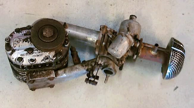 The image below shows a typical endplate made by Ekins: 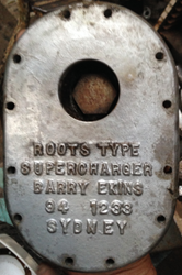 |
|
|
|
|
Logged
|
|
|
|
|
Harv
|
|
« Reply #350 on: June 05, 2016, 05:16:22 PM » |
0
|
Barrys machines were also used in some historic racers, and some ski boats (Barry was interested in skiing as a hobby). The majority of Barrys works were done in 1968. Barry remembers supercharging a new Holden Monaro (probably a HG or HT). The customer wanted the largest setup available, and despite Barrys advice a supercharger and manifold was imported from the US
costing half as much again as the new vehicle price. The kit was removed after one years use due to the high fuel costs. When Barry ceased his supercharger work he pursued his own Volkswagen service business. Most of the manifold moulds have since been destroyed. The BLOW it Man article below, from The Australian Hot Rodding Review of November 1968 shows some of Barrys work. 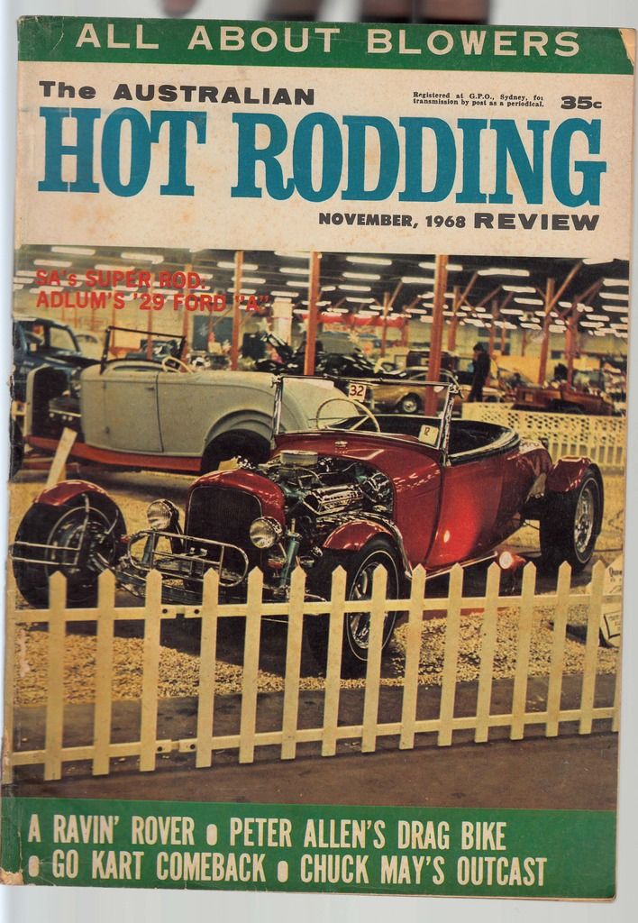 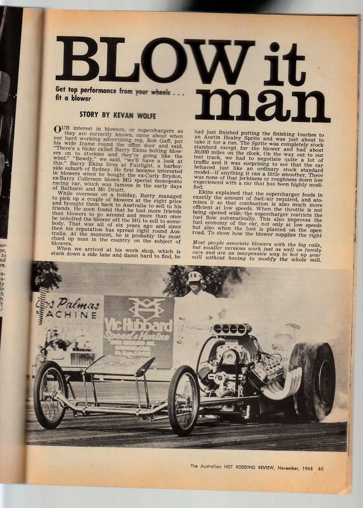 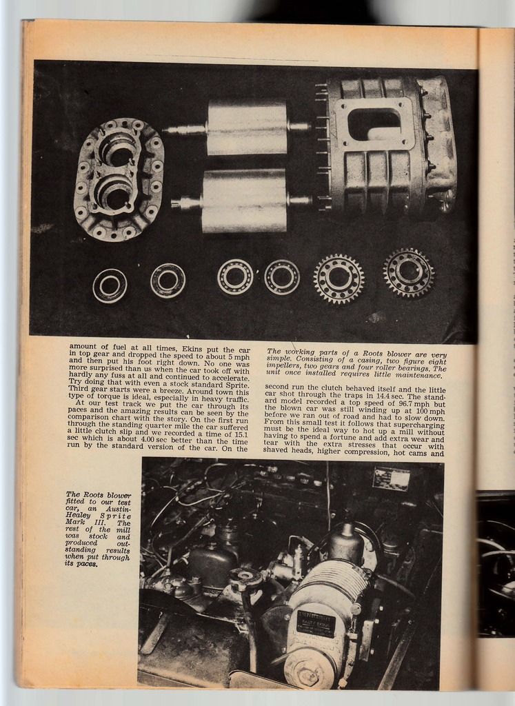 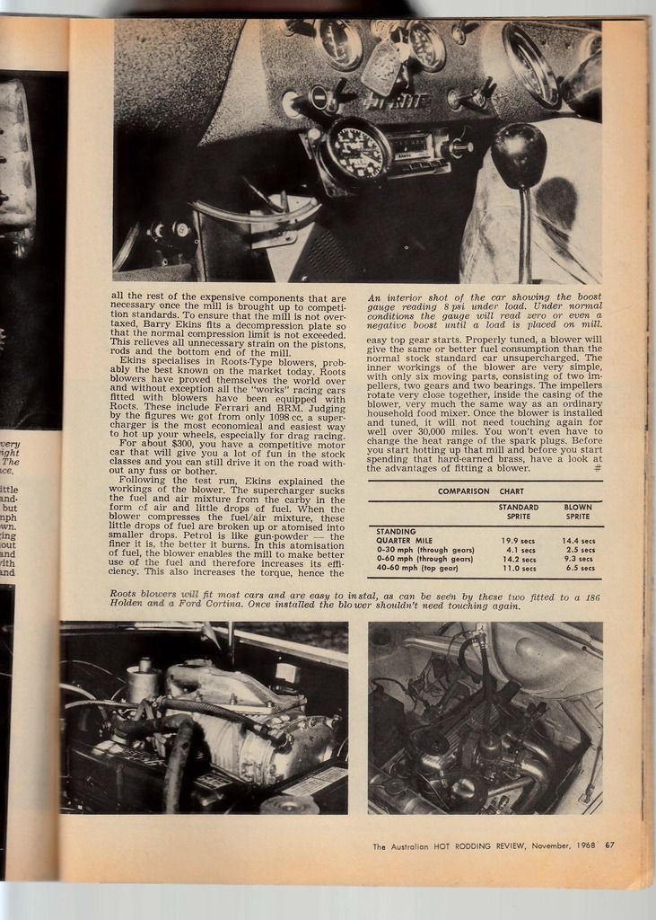 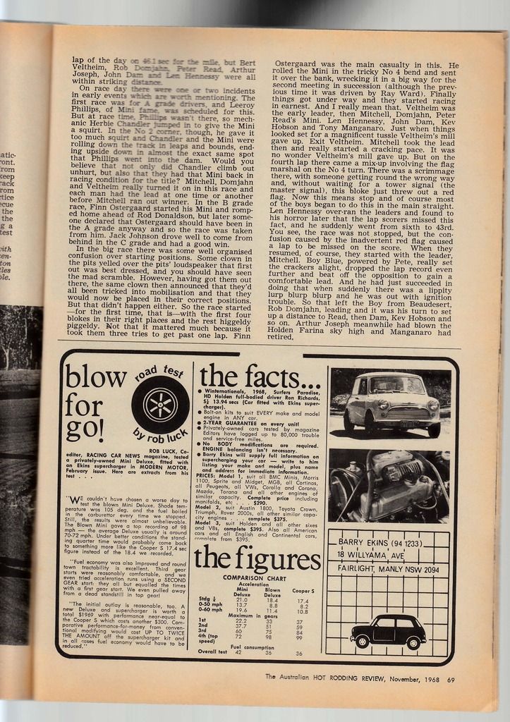 Cheers, Harv |
|
|
|
|
Logged
|
|
|
|
|
Harv
|
|
« Reply #351 on: June 10, 2016, 01:31:17 PM » |
0
|
Ladies and Gents, Wanna see something cool  ? I have owned my Type 110 Norman for quite a while
pulled it apart, measured bits etc. In all that fiddling, I missed something until Fred pointed it out (many thanks Fred). On the non-drive end of the Type 100, a fitting has been made that screws into the end of the rotor. 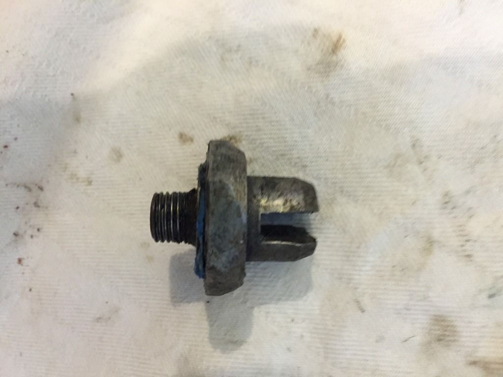 The rotor non-drive end normally has a rotor keeper screwed into it (see my earlier posts). The fitting in my Type 110 replaces the rotor keeper, and has a bayonet fitting at the end. The bayonets protrude past the end of the casing. 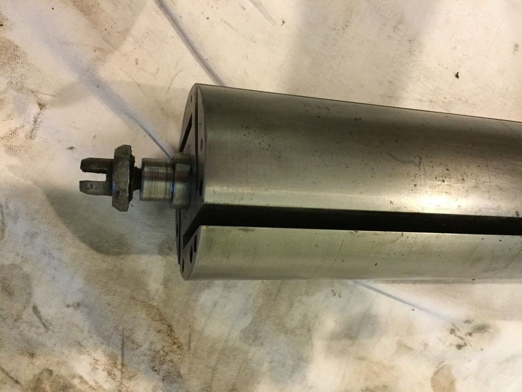 The purpose of the fitting is to provide a drive for a fuel pump (to suit mechanical fuel injection). Fuel pump drives are typically hex drive, as per the photo below (which I have borrowed from the HAMB): 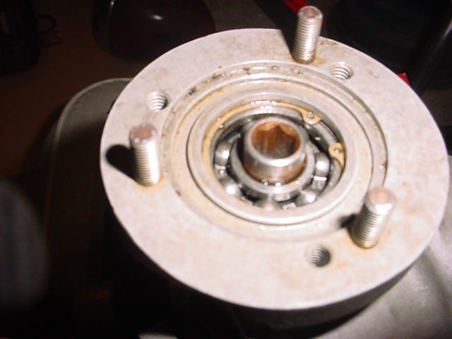 Older fuel pump drives however were tang drive, as per the photo below (again borrowed from the HAMB): 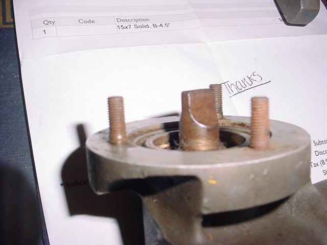 The tang from the fuel pump engages the bayonet on the supercharger fitting. This allows you to bolt a fuel injection pump (eg Hilborn, Enderle, Crower) to the rear of the Norman. The crank drives the supercharger, and the supercharger drives the fuel pump. This saves having to drive the fuel pump from either the distributor/magneto, the camshaft end, or the crank. Whose up for a Norman blown, injected grey ? Cheers, Harv |
|
|
|
|
Logged
|
|
|
|
|
|
|
Harv
|
|
« Reply #353 on: June 21, 2016, 04:01:00 PM » |
0
|
Ladies and Gents, Every now and then something unusual comes along. This was one of those weeks. Some time ago Matt purchased a Type 65 Norman. He had weighed the bare supercharger, and came up with a very low number 10.8kg. This sounded a bit funny to me, as Garys Type 65 was a hell of a lot heavier 20.5kg with the carb hanging off it. The Type 65's were made in four different formats: a) Air-cooled Standard models, having a cast iron finned casing and a steel rotor. b) Water-cooled Standard models, having a cast iron casing with a water jacket welded on, and a steel rotor. c) Lightweight models (LW), which change to an aluminium casings (cast iron or steel lined), having an integral cast water jacket yet retained the steel rotor. d) Super Lightweight (sometimes labelled as Super-Lite), having aluminium casings, tufftrided cast iron or steel liners and a lightened tufftrided steel rotor. The Super Light Weight rotors were made from steel, initially milled from a billet, then with steel flat bar electric stick welded in place with the whole assembly then machined
no small task! A kerosene-fired forge (with a Type 45 supercharger blowing air through it) was then used to heat treat (normalize) the rotors (I own that Type 45 forge blower  ). A Super Light Weight rotor, in an early Type 65 casing, is illustrated in Eldred's Supercharge! booklet: 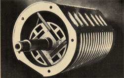 In an advertising brochure, Eldred listed the Type 65 Standard models as weighing 25kg, the Lightweight models as weighing 16kg, and the Super Lightweight as weighing 13kg. Gary's Type 65 is a Lightweight model, and weighs 20.5kg with the carb and drive pulley on. Eldred reckoned it should weigh 16kg, not 20.5kg. There is perhaps a kilo or two in the carb and manifold, so close enough. What caught my attention about Matts is that it weighs 10.8kg. Allow a few kilos (as per Gary's) would suggest that the machine may have be a Super Lightweight, with the funky rotor. Some mechanical investigations by Matt shows something cool his Norman has an aluminium rotor, with the bare rotor weighing in at 5.6kg. Ians standard steel Type 65 rotor weighs 9.6kg - 4kg more than Matt's. Matts ally rotor, shown below, is the only ally Norman rotor I have seen (other than the later 3-vane ones made by Mike), as almost all Eldreds are steel. 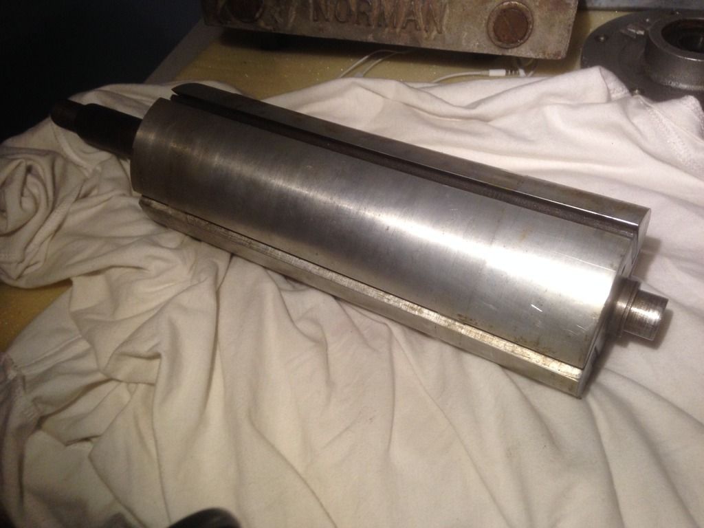 The ally rotors are noted in a number of places: From the Blow! For Go article, Australian Hot Rod November 1966: Eldred has made up several in forged aluminium on special requests but says that a considerable amount of research has proved conclusively that the steel rotor has up to eight times the life of its alumium counterpart, so steel it is. From the Blowers for Holdens! article, The Australian Hot Rodding Review January 1967: "The new series has steel vanes rather than the previous alloy, to cut down the wear factor" From the GO! With Safety brochure: "The steel rotor is used in preference to an aluminium one as it's wearing qualities are very much superior. Naturally, it is heavier, but because of its comparatively small diameter the additional weight is of little disadvantage when accelerating." From a Pricelist, June 30th 1968: Owing to the poor wearing qualities aluminium rotors will not be supplied with any of these units. The 'Tufftrided' steel rotor is only fractionally heavier than aluminium and has at least 12 times the life". From Eldred's Supercharge!: "This type of supercharger has also got a bad name as many of them are made with aluminium rotors, both for reasons of lightness and of cost. Unfortunately this material has very poor wearing qualities as well as causing high frictional loads. The steel rotor has almost eight times the life of its aluminium counterpart and involves much less friction. Also the steel rotor can be nitrided by a new low temperature process which more than doubles the life again, as well as increasing the resistance to fatigue stresses. The steel rotor can be made almost as light as aluminium by a rather complex machining process." All up Matt has a pretty unique, very early rotor. Cheers, Harv (deputy apprentice Norman supercharger fiddler). |
|
|
|
|
Logged
|
|
|
|
|
Harv
|
|
« Reply #354 on: June 23, 2016, 01:48:48 PM » |
0
|
Ladies and Gents, Looks like another aluminium rotor Type 65 has turned up. Teds air cooled cast iron Type 65 (serial number 513, which I have posted previously) also has an alloy rotor, and weighs in at 15kg for the bare supercharger. 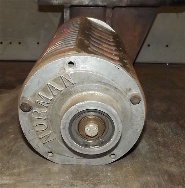 Eldreds weight for the cast-iron casing steel rotored Type 65 was 25kg, though this is probably the water cooled variant (the water jacket adding a few kilos, let alone the steel rotor). Cheers, Harv |
|
|
|
|
Logged
|
|
|
|
|
|
|
GreyFC
|
|
« Reply #356 on: June 25, 2016, 01:29:37 PM » |
0
|
|
|
|
|
|
Logged
|
|
|
|
customFC
nsw-club
Guru

 Offline Offline
Model: FC
Posts: 5904
Ask me about microwaving cats for fun or profit.

|
|
« Reply #357 on: July 04, 2016, 10:19:02 PM » |
0
|
 Australian Hot Rod magazine Jan 1969. Regards Alex |
|
|
|
|
Logged
|
|
|
|
|
Harv
|
|
« Reply #358 on: July 05, 2016, 07:53:56 AM » |
0
|
Damn that's cool . There is very little literature on the Type 110. Interesting that they were water cooled - I had always thought my Type 110 water jacket was added by a previous owner. Now who's up for 145mph in an HD ute? Cheers, Harv |
|
|
|
|
Logged
|
|
|
|
|
Harv
|
|
« Reply #359 on: September 11, 2016, 02:41:28 PM » |
0
|
Ladies and gents, As part of my meth-monster project, I decided that I would fit an aftermarket camshaft to the Norman-blown grey. Whilst the bog-stock grey motor cam is fine for normal street use, the intent for the meth-monster is to flog the living hell out of the motor at the drags. After some digging around, I had a conversation with Clive from Clive Cams. The intent was to custom re-grind the cam to maximise valve lift, and increase exhaust duration whilst minimising overlap where possible. The grind that Clive came up with is shown below - the standard grey motor camshaft specs are in black, whilst those for the meth-monster cam are in red: 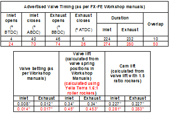 As we can see, Clive has held both the exhaust and inlet valves open longer. For our inlet valve, we get the diagram below (using the Advertised numbers), with the bog-stock grey motor shown in dark blue and the meth-monster cam shown in pale blue: 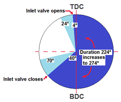 For our exhaust inlet valve, we get the diagram below (again using Advertised values), with the bog-stock grey motor shown in dark green and the meth-monster cam shown in pale green: 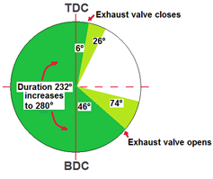 The increased durations will help the motor breathe, as will the increased valve lift. The only drama here is the increased duration, as per the diagram below: 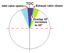 In a supercharged engine with high overlap, what tends to happen is that the pressurized inlet charge blows into the cylinder and straight out the open exhaust valve. This will give poor economy and poor emissions performance, and can lead to a loss of performance at low engine speed where boost is low. It will also have an increased tendency to bang the blower
my meth-monster relief valve will get a bit of a workout. Additionally, increasing overlap will also reduce the boost pressure. Imagine that I started the meth monster with 10psi of boost pressure and the standard GMH cam. Fitting the Clive cam will drop boost pressure down to about 5psi of boost. 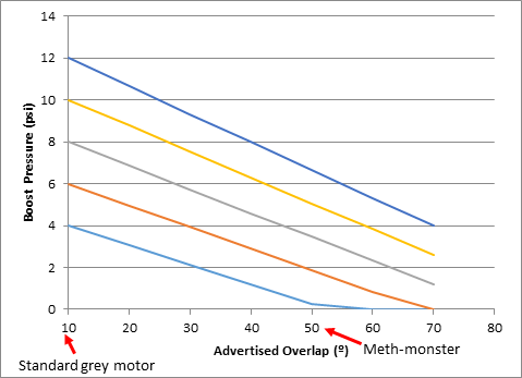 This will then become a balance - the overlap may be of help at high RPM (like the meth-monster on the drag strip), but will lead to a low boost, sluggish vehicle at low RPM. Will the boost loss be outweighed by the increased duration? Hard to tell without putting the vehicle on the long black dyno. The table below weighs up the meth-monster cam (in red) against some commercially available grey motor (naturally aspirated) performance cams: 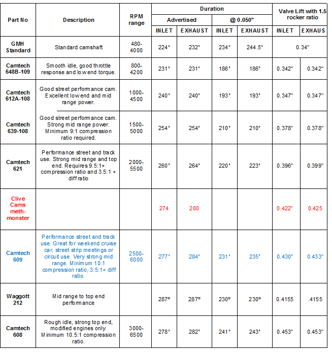 Interestingly, for the same meth-monster service Camtech recommends the Part Number 609 camshaft shown in the table above in blue. Whilst this is very similar in duration to the Clive cam, Camtechs overlap is larger (64º compared to the 50º for the Clive cam), indicating that Clive has got clever in minimising overlap (targeting earlier exhaust opening and later inlet closing, rather than later exhaust closing and earlier inlet opening). Even with Clives magic, 50º is a lot of overlap for a blown motor. Compare for example the supercharger camshafts available from Lunati for small block Chevrolets the advertised overlap is reduced from a typical factory SBC value of 35º to nil, with even their all-out blower cam only having 25º of overlap. So what did I end up with? A cam that is going to help with the top end, though is likely to be sluggish down low and lift the relief valve a fair bit. The plan at this stage is to screw the engine together with a stock grey cam, have a play, then fit the Clive cam later. Ill share the results as they come in. Cheers, Harv (deputy apprentice Norman supercharger fiddler). |
|
|
|
|
Logged
|
|
|
|
|


