FE 4 ME
qld-club
Senior Member

 Offline Offline
Model: FE
Posts: 451
"A Sweet Sensation"

|
 |
« Reply #20 on: September 11, 2011, 03:11:23 PM » |
0
|
Hi there guys, i know this thread is a little old, but my question is/are ... is a standard VN or any later wiper motor ( with intermittent speed ) a 3 speed motor ? So when installing this or any other wiper switch, does it have to be a 3 speed/mode switch to enable the intermittent mode to work ? does it have a built in relay or something in the motor ( or wiring ) to have this option to work  i've sourced a 2 spd with intermittent mode ( which i thought is than a 3spd ) and i'm trying to workout what kind of switch i than can use (will a 3 speed/mode switch need to be used to use the intermittent mode ? or will a 2 spd switch like out of a HR suit ? ). Hoping to try and keep the stock wiper knob on the dash or is the above switch on this thread a 3 speed/mode wiper switch, thus the intermittent mode will work ? I ask guys for your advise and hope my questions might also help other's out there in the same position to upgrade their wiper motor with better electric motor options and a clearer understanding thankx in advance FE 4 ME |
|
|
|
|
 Logged
|
$$$ Parts Catalogue 1948-1969 for sale ONLY $15 $$ all Money goes to the FE/FC Club QLD PM Me to get this great Catalogue
|
|
|
brett_f
Senior Member
Offline
Model: FC
Posts: 561
I love YaBB 1G - SP1!
|
|
« Reply #21 on: September 11, 2011, 07:08:48 PM » |
0
|
FE 4 Me,
The wiper motor is simply a two speed. The intermittent is run via relays and computer so the normal switch willl not convert to intermittent on an FC.
Regards Brett
|
|
|
|
|
Logged
|
|
|
|
FE 4 ME
qld-club
Senior Member
Offline
Model: FE
Posts: 451
"A Sweet Sensation"
|
|
« Reply #22 on: September 11, 2011, 08:12:21 PM » |
0
|
Thankx Brett, That now makes it a lot clearer and a little easier for me to understand and to work with, so i gather my 1st car ever was a ( Block your ears fellas ) 1980 model F#%d Escort Panelvan and it's wiper must of had a set of relays to make the intermittent mode work.. computers were at best a commodore 64 or 120 for the rich people  so it had to be relays... i wonder how hard it would be to set it up on a FE thankx for your input FE 4 ME |
|
|
|
|
Logged
|
$$$ Parts Catalogue 1948-1969 for sale ONLY $15 $$ all Money goes to the FE/FC Club QLD PM Me to get this great Catalogue
|
|
|
cruisin_doug
Newbie
Offline
Model: other Holden
Posts: 24
|
|
« Reply #23 on: July 02, 2012, 08:46:01 AM » |
0
|
Just like to thank Brett and the other contributors for the info, hope you don't mind I have added a link to the FX FJ site as there is good info here needed by plenty.
Cheers
Doug
|
|
|
|
|
Logged
|
|
|
|
|
Sparkie
|
|
« Reply #24 on: August 10, 2013, 10:13:46 PM » |
0
|
hi have followed instructions and now need to fabricate the special crank arm(s) that come off back of motor.Would someone be able to measure up this item maybe with a picture as this would be a great help to me and also future people doing this conversion who are also not being able to locate EK holden setup.Thanks again for handy post GARY |
|
|
|
« Last Edit: August 10, 2013, 11:04:37 PM by stinky »
|
Logged
|
|
|
|
|
hsv-001
|
|
« Reply #25 on: August 18, 2013, 03:57:11 PM » |
0
|
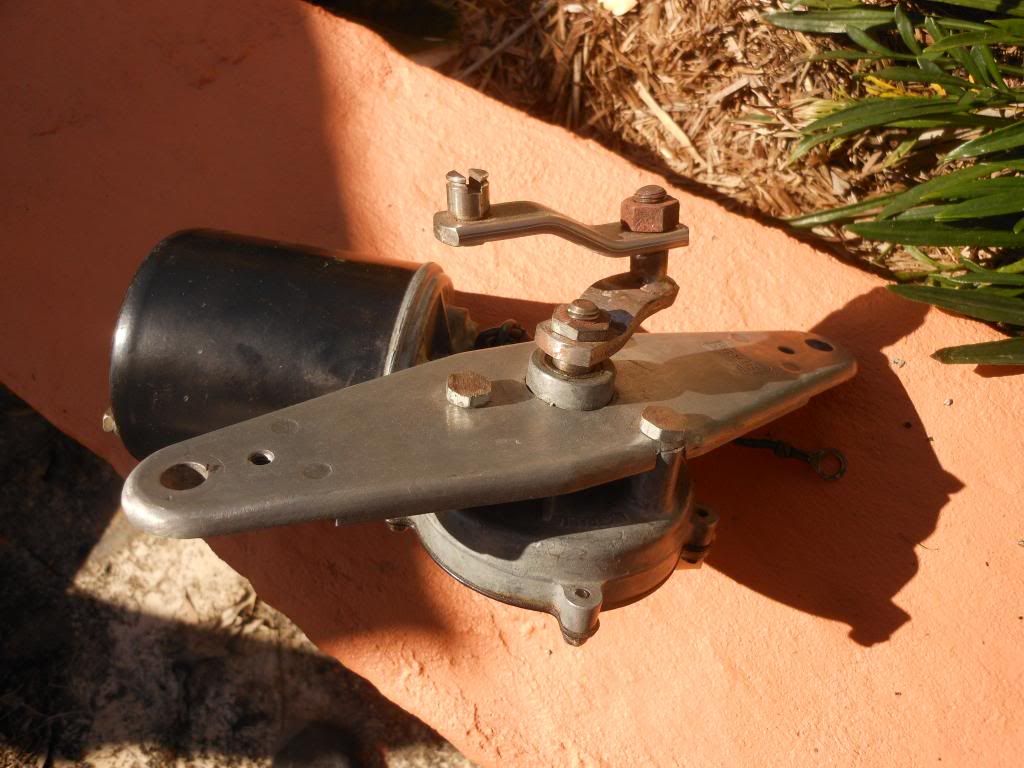
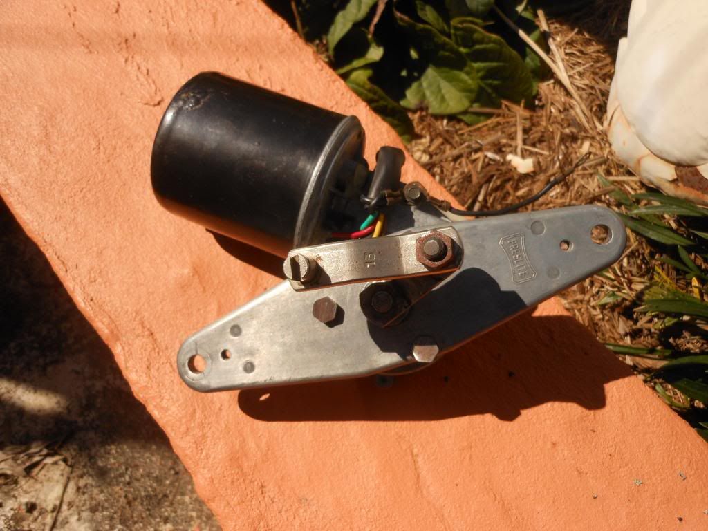
When I thought I might build a spare wiper motor unit out of a commodore wiper motor [my existing one out of a nissan started making noises and the wipers were slapping badly] I found the original vacuum unit and measured the radius from centre of the drive.In other words the short bracket as I was not sure if the EK was the same as the windshields are different and thought this may explain some of the slapping. The second bracket[the longer bracket] has to face in nearly the opposite direction but not exactly ,around 135 degrees not 180 degrees as it would jam at the opposing points. The second bracket has to be slightly shorter [only a few thou.]as its shaft has to be the same distance from the motor drive shaft as the first bracket. Anyway it works so I'll keep it as a spare because when I went to install it I found a lot of play caused by a displaced bush on the motor output shaft and the mounting bolts were loose and had to bend a wiper arm that was hitting . So all is sweet with the Nissan motor so no prob'. I can get photos or measurements for you if needed.
|
|
|
|
|
Logged
|
|
|
|
|
Sparkie
|
|
« Reply #26 on: August 18, 2013, 07:56:31 PM » |
0
|
thanks for info,my plan is to use the VN wiper arm pivot shafts for the crank shafts which have the tapered spined ends which will enable me to adjust the angle on second crank.Do understand that both cranks need to be the same so if you could measure between centre points of first crank[that is centre of wiper shaft to centre of hole] that would save a lot of time.Was thinking of setting up wiper arms and physically moving arms over windscreen and measuring at wiper motor point ,how far it travels in a straight line.Once getting that measurement I think I would half that measurement and that would be the length of crank I would require.As I haven,t a windscreen fitted yet I was planning on forgetting about for a while as no one seemed interested in helping.Thanks again for input and as said before that measurement would be handy if you have time to do so ,GARY
|
|
|
|
|
Logged
|
|
|
|
|
hsv-001
|
|
« Reply #27 on: August 19, 2013, 01:07:37 PM » |
0
|
For some reason their not the same. As I said before, it seem like the second bracket is offset from the centre[not over motor drive shaft centre] and the second bracket is not twice the first, maybe this is so they don't get jammed at the max. of the stroke. Anyway the first one measures 28mm and the second 50mm, this is centres. I'm not sure about making the brackets from commodore parts though and am uncertain what my brackets were made up from as I found the pieces in some buckets of bolts I had for years. Also the first bracket is splined to the motor and has a splined bolt on the other end , then the second bracket is splined to the first but just has the retaining clip at the other. I believe rares has these clips. I'll try and post a picture later today.
|
|
|
|
|
Logged
|
|
|
|
brett_f
Senior Member
Offline
Model: FC
Posts: 561
I love YaBB 1G - SP1!
|
|
« Reply #28 on: August 19, 2013, 04:10:36 PM » |
0
|
Gary, Ive sent you an email with some pics that might help you out. Regards brett
|
|
|
|
|
Logged
|
|
|
|
|
Sparkie
|
|
« Reply #29 on: August 19, 2013, 07:33:22 PM » |
0
|
Thanks Brett, yes what you sent is just what I need and very much appreciated. GARY
|
|
|
|
|
Logged
|
|
|
|
|
hsv-001
|
|
« Reply #30 on: August 19, 2013, 07:49:40 PM » |
0
|
  thought this might be helpful. |
|
|
|
|
Logged
|
|
|
|
|
Sparkie
|
|
« Reply #31 on: August 20, 2013, 07:17:11 AM » |
0
|
thanks for that,Brett has said the first crank[off motor] measures 0ne inch and second is two inches so with pictures it makes it great for everybody .First crank goes to left arm ...GARY
|
|
|
|
|
Logged
|
|
|
|
|
Luke Healey
|
|
« Reply #32 on: March 02, 2017, 12:04:23 PM » |
0
|
Not sure if this is an original arm from the fc or not but this is how i have modified the vr arm to suit. I cut the ball end off the vr arm. Drilled two holes and filed for an hour to make it a rectangle. I now need to get a milling drill bit so i can make a flat area for the nut to come up to. Using this arm makes up for the short shaft on the vr wiper motor.    Sent from my SM-G900I using Tapatalk |
|
|
|
« Last Edit: March 10, 2017, 09:28:05 AM by stinky »
|
Logged
|
|
|
|
|
Luke Healey
|
|
« Reply #33 on: March 02, 2017, 04:31:03 PM » |
0
|
 Sent from my SM-G900I using Tapatalk |
|
|
|
|
Logged
|
|
|
|
|
Luke Healey
|
|
« Reply #34 on: March 02, 2017, 04:33:06 PM » |
0
|
  Its close to the fire wall but clears. Now to get a switch and use bretts wireing diagram Sent from my SM-G900I using Tapatalk |
|
|
|
|
Logged
|
|
|
|
|
mcl1959
|
|
« Reply #35 on: March 02, 2017, 06:59:28 PM » |
0
|
This is how I do it  You will find that the wiper arm also needs to clear the sound deadening board. I cut the Commodore arm in half and the EK one in half, bend them and fit them up in my jig and weld them together. Ken |
|
|
|
|
Logged
|
|
|
|
|
camxsmith
|
|
« Reply #36 on: March 02, 2017, 07:36:38 PM » |
0
|
This is how I do it You will find that the wiper arm also needs to clear the sound deadening board. I cut the Commodore arm in half and the EK one in half, bend them and fit them up in my jig and weld them together. Ken Hi Ken Could you supply the measurements for your little arm ,, or have you already post them else where.  |
|
|
|
|
Logged
|
|
|
|
|
Luke Healey
|
|
« Reply #37 on: March 02, 2017, 08:40:03 PM » |
0
|
I have made th the plate out of 2mm steel to reduce the gap and replaced the metal spacers with just rubber ones. Will still be using the sound deadiner
Sent from my SM-G900I using Tapatalk
|
|
|
|
|
Logged
|
|
|
|
|
Luke Healey
|
|
« Reply #38 on: May 19, 2017, 05:03:53 PM » |
0
|
So the final install of a vr wiper motor all working. No switch yet... 2mm steel base plate Shortend the vr arm, drilled new hole filed square hole counter sunk nut in square hole. Mushroom screws used to mount motor to base plate to bring it closer to the fire wall. Installed with rubber washers and rubber back plate.      Sent from my SM-G900I using Tapatalk |
|
|
|
|
Logged
|
|
|
|
|
Errol62
|
|
« Reply #39 on: May 19, 2017, 06:46:03 PM » |
0
|
Handy fabrication skills there whealy. Saves pillaging an ek wiper motor for the base and the arm as well.
Sent from my iPad using Tapatalk
|
|
|
|
|
Logged
|
|
|
|
|


