FE-FC Holden Discussion Forum
May 15, 2024, 01:36:33 AM *
Welcome, Guest. Please login or register.

Login with username, password and session length
News: The FE-FC Holden Car Club of NSW are proud to host the 19th FE-FC Holden Nationals. Check out the announcement video for more.
 
   Home   Help Search Calendar Login Register  
Pages: [1]   Go Down
  Add bookmark  |  Print  
Author Topic: Grey motor pushrod investigations  (Read 12468 times)
Harv
Guru
*****
Offline Offline

Model: other Holden
Posts: 1321


View Profile
« on: July 16, 2015, 09:23:54 AM »
0

Ladies and gents,

The notes below are from a small side project I did looking at grey motor pushrods.  I got interested after Ellis recently had some new pushrods made. Hope the info below is of interest.

Three different types of pushrod were offered for the Holden grey motor.
• Part number 7401247 up to FJ engine 178123,
• Part number 7408422 from FJ engine 178124 through to FB engine B65279. I am uncertain as to why this change was made or the difference in the pushrods as no change was made to the lifters (anyone know?), and
• Part number 7416291 from FB engine B65280 through to the end of the EJ. This pushrod came about because the lifter ball seat was raised 3/16”, and the pushrods shortened by the same amount to an overall length of 10 1/8”.


The humble grey motor pushrod has a relatively simple job to do. At one end, it follows the lifter, moving up and down as the lifter itself rolls over the camshaft lobe. At the other end, it is moving up to push the rocker (and open the associated valve), and then following the rocker back down under valve spring tension. In an ideal world, the pushrod is just a simple vertical column of steel under a cyclic compression load. Steel is damn strong under compression – it takes around 150 megapascals (22,000 psi) to get steel to yield and mushroom out.
Unfortunately, the humble pushrod is far from ideal. Interaction with the lifter at one end, and the rocker at the other, can put bending (rather than compressive) loads on the pushrod. This is particularly true for the rocker end of the pushrod, as the rocker moves in an arc.


The Holden grey motor pushrod is relatively robust. However, it is not uncommon to bend them. Note that the damage seen is a distinct bend in the middle of the pushrod, rather than the mushrooming that would be seen in purely compressive failure.
Along with the interaction with the lifter and rocker, there are other sources of bending forces on a pushrod.
a) At high rpm, the lifter can jump off the end of the cam, leading to increased loading on the pushrod when the lifter smacks back down onto the cam lobe. This type of loading can also occur at the other end of the pushrod due to valve float (when the valves are moving so fast they don’t quite seat) and valve bounce (where the valves are moving so fast they smack the valve seat then bounce open a bit).
b) Sticking valves (from poor valve clearances, poor tolerances when machining, coke build-up, or corrosion from an engine that has sat a long time) and backfires can all make the valve (and rocker) want to be in a place that the pushrod isn’t ready for, leading to increased loading.
c) The standard valve spring pressure for a grey motor is 98-110 lbs. (valve open) and 48-54 lbs (valve closed). Valve spring pressure is often increased in order to remedy valve float. This is done by replacing the standard grey motor valve springs with stiffer springs, either single or double.  Whilst the stronger springs help keep the valve closed, they also impart additional loading on the pushrod (and can also lead to increased valve bounce).
d) For increased flow, a common modification is to increase the valve opening by regrinding the camshaft to give increased lift. Care needs to be taken that the increased lift does not put the selected valve springs into bind. Spring bind (or coil bind) is where the spring has compressed as much as it can… but the cam wants to lift the valve more. This puts a significant bending load on the pushrods.
Logged
Harv
Guru
*****
Offline Offline

Model: other Holden
Posts: 1321


View Profile
« Reply #1 on: July 16, 2015, 09:24:27 AM »
0

One option that is used in some grey motors to prevent pushrod bending is to convert the pushrods to larger diameter units. The larger diameter resists bending better, though can lead to an increase in weight. Bear in mind that at the nominal  stock grey motor redline that a pushrod is accelerating from standstill and back to a dead stop again 75 times a second. It takes energy to undertake this acceleration and deceleration – the heavier the pushrod, the more energy lost. To regain some of the weight of larger diameter pushrods, the pushrods are often made hollow. There is then a trade-off between the strength and weight  gained in greater pushrod diameter, and the strength and weight lost in hollowing them out.

Aftermarket pushrods are also often made of steels that have been alloyed with chromium and molybdenum (chrome moly, moly, CrMo or chromalloy). Chrome moly steels have a better higher temperature strength than steel, and slightly better corrosion resistance. However, at room temperatures they are not a “miracle steel”, despite the legends that surround them. For example,
a) One rumour is that chrome moly steels are lighter than carbon steels. This is not correct – they are both roughly the same weight (about 7.85 times heavier than water). A tube of carbon steel weighs exactly the same as a tube of chrome moly steel of the same dimensions.
b) Another rumour is that chrome moly steels are stiffer than carbon steels. This is also not correct – they both have roughly the same resistance to being bent (a Young’s Modulus around 210 gigapascals or 30,000,000 psi). A tube of carbon steel will bend just as much as a tube of chrome moly steel of the same dimensions.
Where chrome moly comes into play is that it has a higher yield stress (around 435 megapascals, or 63,000 psi) than carbon steel (around 280 megapascals or 41,000 psi). If we imagine our carbon steel tube above, we can apply a force to it and it will bend, then snap back like a spring once the force is taken away. If we keep increasing the force, eventually we permanently bend the carbon steel tube. If we do the same thing with the chrome moly steel tube, it will take twice as much force before it permanently bends.

So in short, a chrome moly component is no lighter, nor any stiffer than a carbon steel one. It just takes twice as much punishment before it permanently bends.
As a side note, compare this with a titanium alloy like Ti-6Al-4V. It is almost half as light as carbon steel (4.43 times heavier than water), will bend twice as much as carbon steel (a Young’s Modulus around 115 gigapascals or 17,000,000 psi), but will take three times the beating before deforming (a yield stress around 880 megapascals or 128,000 psi).

So what happens when we take a solid, mild steel pushrod and change it to a hollow chrome moly pushrod of different diameter? There are a few things we are playing off here:
a) A hollow pushrod is lighter than a solid one. This relieves stress on the reciprocating valve train.
b) A hollow pushrod will take less load than a solid one. It will bend more, and permanently bend before a solid one will.
c) A smaller pushrod diameter will take less load than a larger diameter one, and permanently bend before a larger diameter one will.
d) A chrome moly pushrod will still spring like a steel one… but will take twice the loading before it permanently bends.
Logged
Harv
Guru
*****
Offline Offline

Model: other Holden
Posts: 1321


View Profile
« Reply #2 on: July 16, 2015, 09:25:37 AM »
0

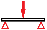
So how do we balance this up? Modelling a pushrod that is being bent in compression is not an easy thing. Equally, we don’t need answers to seven decimal places. The easiest way to model a bending pushrod (and accurate enough for what we are doing) is to treat the pushrod like a simple beam being bent:


Assuming a pushrod with outside diameter D, and for the hollow ones with an inside diameter d,
a) The bending load on the solid pushrod is inversely proportional to the diameter4. For the hollow pushrod, it is inversely proportional to (the difference in inner/outer diameter)4.
i.e. stress α 1/D4 for the bar, and stress α1/(D4-d4) for the pipe.
b) Weight is proportional to the diameter2 for the solid pushrod, and proportional to (the difference in inner/outer diameter)2 for the hollow one.
i.e. weight α D2 for the bar, and weight α(D2-d2) for the pipe.

As examples, taking a solid 3/8” pushrod and increasing the diameter to 7/16” will halve the bending stress in the pushrod, but increase weight by a third. Replacing the same 3/8” pushrod with a 7/16” hollow pushrod with 0.080” wall thickness will reduce the stress by 40% (less than the 50% of the solid 7/16” ones), but will reduce weight by 20% (compared to the 33% increase in weight of the solid 7/16” ones).

One trick that the racing fraternity has been using for some time is to cut the ends off old hollow pushrods, and insert a thinner tube into the two old ends. This was recently done by Ellis, using some 0.035” walled chrome moly tubing. Looking at Ellis’ new pushrods:
a) original solid pushrods are 0.252” outside diameter
b) replacement pushrods are 0.372” outside diameter and 0.035” wall thickness (0.302” internal diameter).
Ellis’ pushrods have only one third of the bending stress than the original GMH pushrods, and will be some ¾ of the weight.

An alternative would be to take the standard GMH pushrods, cut the ends off and slip the ends into a larger chrome moly tube. The resultant pushrod strength (and weight) would depend on what tube wall thickness is used. As a guide for this scenario:


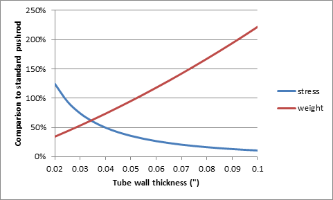
The graph above shows that tube wall thicknesses of 0.024” and thicker would have the same or less stress than the standard pushrod, whilst wall thicknesses of 0.052” or thinner would have the same or less weight than a standard pushrod. In short, if you want to take a standard grey motor pushrod, cut the ends off and insert them into hollow chrome moly steel tubes, the wall thickness “sweet spot” range is between 0.024-0.052”.

As a comparison, looking at some typical pushrod manufacturers:
• Manton make pushrods in  0.035-0.168” wall thickness (3/8”-7/16” outside diameter),
• Trend make 0.080-0.188” (5/16”-3/16” outside diameter),  whilst 
• TrickFlow make 0.080”-0.135” wall thickness (5/16”-3/8” OD).

Cheers,
Harv
Logged
ardiesse
nsw-club
Guru
*****
Offline Offline

Model: FC
Posts: 1299


View Profile
« Reply #3 on: July 16, 2015, 05:50:10 PM »
0

Harv,

I've just put together a parts-bin-special 3-3/16-bore motor, and I discovered the lifter-and-pushrod problem by experience.
Stan Bennett's humpy-Holden "Scrapbook" series describes the changes (and I'm going from memory here) -

The change made part-way through FJ production was to improve the rocker geometry.  I think it was to shorten the pushrod by about a millimetre, because the valves changed to incorporate a stem oil seal, and the valve stems were lengthened slightly.  At about the same time, the insert in the inside of the cam follower was deleted, although the newer cam follower was dimensionally identical to the old one.  This state of affairs continued until the half-way-through FB change to shorter pushrods and thicker ball seats on the followers.

The head (and probably block) on this motor had been machined down so much that the thermostat housing and the water pump interfered with each other, and some of the pushrods bound on the rocker arms at full lift, because I had to unscrew the adjuster so far.  These pushrods, I found, were the "early early" type, and when I replaced them with late FJ - early FB types, it was ok (just).  And then I needed flat washers under the long head bolts so they didn't bottom in the block . . .

Rob
Logged

Remember: if your Holden's not leaking oil, it doesn't have any.
Harv
Guru
*****
Offline Offline

Model: other Holden
Posts: 1321


View Profile
« Reply #4 on: July 16, 2015, 06:33:21 PM »
0

Cool - thanks Rob.

Cheers,
Harv
Logged
mcl1959
vic-club
Guru
*****
Offline Offline

Posts: 6155


FE's rule


View Profile
« Reply #5 on: July 16, 2015, 08:20:54 PM »
0

I looked it up and the change in length from the first type to the second type is 0.08 inches or just over 1/16 of an inch. Or for the younger readers - 2.03mm
So in metric terms the lengths are approximately as follows
264 mm
262 mm
257 mm

Ken
Logged
Harv
Guru
*****
Offline Offline

Model: other Holden
Posts: 1321


View Profile
« Reply #6 on: July 17, 2015, 06:31:21 AM »
0

Thanks Ken. Out of curiosity, did you reference have the same reasoning as Rob gave above, or just the lengths?

Cheers,
Harv
Logged
Harv
Guru
*****
Offline Offline

Model: other Holden
Posts: 1321


View Profile
« Reply #7 on: July 17, 2015, 09:33:55 AM »
0

Trawling through the MasterParts catalogue, it looks like Stan's explanation of the early humpy pushrod change is right. After FJ engine 178123, the inlet valves change (from part number 7401248 to 7408420), the exhaust valves change (from 7401249 to 7408421) and the valve stem oil seal gets introduced for all future grey motors (part number 3835333).

Cheers,
Harv
Logged
mcl1959
vic-club
Guru
*****
Offline Offline

Posts: 6155


FE's rule


View Profile
« Reply #8 on: July 17, 2015, 07:44:00 PM »
0

Yes, valve length change to include a seal at the top plus mods to the cap.

Ken
Logged
ardiesse
nsw-club
Guru
*****
Offline Offline

Model: FC
Posts: 1299


View Profile
« Reply #9 on: July 21, 2015, 02:09:59 PM »
0

Some further information about the early pushrod-valve-valve cap change (taken from Stan Bennett's Scrapbook No. 5):

Service Bulletin H74-G (Nov. 1954)

Engine Valves, Cap and Seal

"At approximately Engine No. 179672, re-designed inlet and exhaust engine valves and valve spring cap will be introduced in production.  These new valves are 0.060 in. longer in stem length than the previous type and in addition, the valve stem has an extra groove so as to accommodate a synthetic oil seal.  The increased length of the new type valve improves the valve geometry and provides quieter operation, whilst the seal ensures a more positive control over the amount of oil that is required to lubricate the valve guide and stem assembly (see Fig. 1)."

[Figure 1 shows photos of the first type valve cap (inner top face recessed) and the second type valve cap (inner top face dome-shaped)]

The old-type valve cap is part number 839367, and the new valve cap is part number 3835392. (I note that these are both Chev part numbers)

And then -

Service Bulletin H88G (Aug. 1955)

Valve Push Rod (Revised)

"Further to the information contained in Service Bulletin H74-G, regarding the re-designed engine valves, cap and seal, we advise that at the same time the valve push rods were shortened by 0.080 in.  The revised push rod is serviced under Part No. 7408422 and is suitable only for those engines equipped with the longer valve and oil seal."

Rob
Logged

Remember: if your Holden's not leaking oil, it doesn't have any.
Harv
Guru
*****
Offline Offline

Model: other Holden
Posts: 1321


View Profile
« Reply #10 on: July 21, 2015, 06:10:05 PM »
0

Cool - love the GMH history Cool.

Wonder how many guys over the years have stumbled on pushrods that "just won't adjust... no matter how hard I try I run out of rocker thread".

Cheers,
Harv
Logged
KFH
qld-club
Senior Member
****
Offline Offline

Model: FC
Posts: 681


View Profile
« Reply #11 on: July 21, 2015, 07:35:56 PM »
0

One motor I dismantled had two different lengths of pushrods in it.  The adjustments on some of them where at the extremes of their travels.  Obviously somebody made up a motor using bits and pieces from everywhere.

Keith
Logged

I was born with nothing and still have most of it left
Pages: [1]   Go Up
  Add bookmark  |  Print  

Share this topic...
In a forum (BBCode) 
In a site/blog (HTML)

 
Jump to:  

Powered by MySQL Powered by PHP Powered by SMF 1.1.21 | SMF © 2015, Simple Machines Valid XHTML 1.0! Valid CSS!
Page created in 0.04 seconds with 19 queries.